Gypsum Board Suspension System: Dimensions & Load Specs
Master gypsum board suspension system specs. Explore exact dimensions, framing spacing, hanger wire gauges, and ASTM load capacities for ceiling grids.

Core Architectures: T-Grid vs. Channel Systems
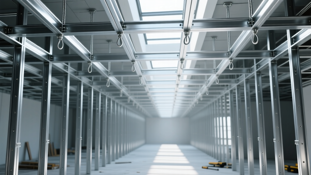
When specifying a gypsum board suspension system, contractors must choose between two primary structural architectures: the Suspended Drywall T-Grid System and the Cold-Rolled Channel (CRC) System. While both serve to suspend gypsum panels from the overhead structure, their dimensional profiles, load-bearing capacities, and installation tolerances differ significantly. Selecting the wrong system—or worse, attempting to use a standard 15/16-inch acoustic ceiling grid for drywall—will result in catastrophic deflection, fastener pop, and joint cracking.
As of 2026, the USG Suspended Drywall Ceiling Systems remain the industry benchmark for T-grid drywall framing, utilizing heavy-duty 1-1/2-inch face tees designed specifically to support the dead load of gypsum board without sagging.
| Component | T-Grid Drywall System | Cold-Rolled Channel (CRC) System |
|---|---|---|
| Primary Member | 1-1/2 in. face main tee (e.g., DXL2) | 3/4 in. cold-rolled channel (CRC) |
| Secondary Member | 1-1/2 in. face cross tee | 7/8 in. furring channel (hat channel) |
| Typical Steel Gauge | 20 to 16 gauge (hot-dipped galvanized) | 25 gauge (CRC), 25 to 20 gauge (furring) |
| Max Main Runner Spacing | 48 in. on center (OC) | 48 in. OC (12-gauge hangers) or 36 in. OC |
| Max Furring/Cross Tee Spacing | 16 in. or 24 in. OC | 16 in. or 24 in. OC |
| Best Application | Large commercial plenums, curved ceilings | Standard commercial, multi-layer heavy ceilings |
Dimensional Spacing and Layout Tolerances
Precision in layout is non-negotiable. The spacing of the suspension members dictates the allowable span of the gypsum board and directly impacts the ceiling's resistance to gravity and lateral loads.
Main Runner Placement
Main runners (whether T-bar tees or 3/4-inch CRCs) must be installed perpendicular to the hanger wires and parallel to one another. The maximum allowable spacing for main runners is 48 inches on center (OC). However, in seismic zones or when supporting heavy overlay loads (such as HVAC diffusers or recessed lighting), reducing main runner spacing to 36 inches OC is highly recommended to minimize deflection.
Furring Channel and Cross Tee Spacing
The secondary members, which directly receive the gypsum board fasteners, must be spaced according to the board thickness and edge orientation:
- 1/2-inch Gypsum Board: Secondary members must be spaced at a maximum of 16 inches OC. Spacing at 24 inches OC with 1/2-inch board will exceed the board's flexural strength, leading to visible sagging between joists.
- 5/8-inch Gypsum Board: Secondary members can be spaced at 16 inches or 24 inches OC. For 24-inch OC spacing, the board's long dimension must be installed perpendicular to the furring channels.
Hanger Wire and Fastener Specifications
The connection between the overhead structure and the suspension grid is the most critical load path in the assembly. Hanger wires must meet strict gauge and installation criteria outlined in ASTM C635 and C636 standards.
Wire Gauge and Spacing Limits
Standard suspended drywall systems require 12-gauge (0.081-inch) galvanized steel hanger wire. For ceilings carrying superimposed loads (e.g., heavy insulation, ductwork attached to the grid, or multi-layer fire-rated assemblies), 10-gauge (0.106-inch) wire is mandatory.
Hanger wires must be spaced no more than 48 inches apart along the main runners. Additionally, a hanger wire must be placed within 16 inches of the end of every main runner. If a main runner is spliced, hanger wires must be located within 6 inches of the splice on both sides to prevent hinge-point deflection.
The 3-Wrap Rule
Wire wrapping is a frequent point of failure in field inspections. The wire must be wrapped around the main runner or CRC a minimum of three full turns within a 2-inch vertical length. The tail of the wire must be bent flat against the wraps. Loose wraps or fewer than three turns will allow the grid to slip under dynamic loads, compromising the ceiling's level plane.
Load Capacities and Deflection Limits
According to Gypsum Association GA-216 guidelines, the entire suspension system must be engineered to support the dead load of the gypsum board plus any superimposed loads without exceeding a deflection limit of L/360 (where L is the span length).
For a standard 48-inch main runner span, the maximum allowable deflection under full design load is roughly 0.13 inches. Exceeding this threshold causes the drywall seams to telegraph through the finished surface, particularly under critical lighting conditions (e.g., wall-washing LED fixtures).
"Suspension systems shall be designed to carry the total dead load of the ceiling assembly, plus a minimum concentrated load of 20 pounds applied at any point, without exceeding L/360 deflection." — Adapted from ASTM C635 Heavy-Duty Classification requirements.
Seismic and Lateral Bracing Dimensions
In regions governed by stringent seismic codes (such as IBC Seismic Design Categories C, D, E, and F), the gypsum board suspension system requires rigid lateral bracing to prevent grid collapse during structural drift.
- Compression Posts: Vertical struts must be installed from the ceiling grid to the structure above at maximum intervals of 30 feet in both directions. These posts must be rigid enough to resist both upward and downward forces.
- Lateral Bracing Wire: 12-gauge splay wires must be installed at a maximum 45-degree angle from the horizontal plane. These wires stabilize the grid laterally and must be spaced no more than 30 feet apart.
- Seismic Separation Joints: For ceiling areas exceeding 2,500 square feet, or where the ceiling length exceeds 150 feet, seismic expansion joints must be integrated into the grid to allow independent movement of separate ceiling planes.
Common Installation Failures and Edge Cases
Even with perfect material specifications, field execution often introduces dimensional errors. Recognizing these edge cases prevents costly rework:
1. Fastener Over-Driving
When attaching 5/8-inch gypsum board to 25-gauge furring channels, using a drill with an improperly adjusted clutch will over-drive the 1-1/8-inch Type S-12 screws. If the screw head breaks the paper face of the gypsum core, the fastener loses 100% of its pull-out resistance. The fix requires adding a secondary screw 2 inches away from the blown-out fastener.
2. Splicing Furring Channels Incorrectly
When 7/8-inch furring channels must be spliced end-to-end, they must overlap by a minimum of 8 inches and be secured with two screws. Furthermore, these splices must be staggered across the ceiling plane; aligning all splices on the same main runner creates a weak hinge line that will inevitably crack the drywall joints above it.
3. Ignoring Plenum Air Pressure
In modern commercial HVAC designs, the ceiling plenum is often used as a return air chamber. This creates negative pressure that pulls upward on the gypsum board. If the suspension system is not specified with hold-down clips or if the perimeter molding is not sealed, the ceiling will visibly lift and chatter when the air handlers engage. Always specify positive-pressure hold-down clips for plenum-return environments.
Written by
James ThorntonJames Thornton is a construction industry veteran with 25 years of hands-on experience in wood framing, lumber grading, and residential building codes. He started as a framing carpenter in rural Oregon, earned his ICC Residential Building Inspector certification, and eventually became a senior plan reviewer for the City of Portland Bureau of Development Services. James holds a B.S. in Wood Science & Technology from Oregon State University and is a certified lumber grader through the West Coast Lumber Inspection Bureau (WCLIB). He has inspected over 3,000 residential construction sites and authored the city's internal guide on advanced framing techniques (2x6 at 24" O.C.). James lives in Bend, OR, where he builds custom timber-frame cabins and competes in lumberjack sports.
More from James Thornton
View all
Insulation
Best Home Insulation Materials: Complete 2026 Guide
Compare top home insulation materials for 2026. Find R-values, installed costs per square foot, and best uses for fiberglass, spray foam, and mineral wool.
Aug 4, 2026

Sustainable Building
Certify Your Green Building Material for LEED and WELL
Step-by-step guide to certifying a green building material for LEED v5 and WELL v2. Master EPDs, HPDs, and VOC limits for 2026 project specifications.
Aug 4, 2026

Stone & Masonry
Veneer Stacked Stone Panels: Interior Design & Style Showcase
Discover how veneer stacked stone panels transform interiors. Explore modern design profiles, material pairings, and technical installation specs.
Aug 4, 2026