Cold-Formed Steel Framing for Load-Bearing Structural Walls
Explore cold-formed steel framing for load-bearing structural walls. Compare gauges, ASTM standards, and costs for mid-rise commercial builds.

Engineering Cold-Formed Steel Framing for Structural Loads
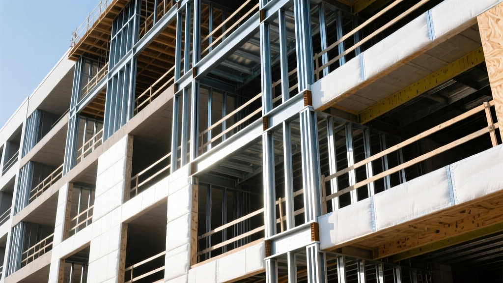
When transitioning from non-load-bearing partition walls to structural applications, cold-formed steel (CFS) framing requires a fundamental shift in material specification and engineering oversight. Structural steel framing relies on high-strength, cold-rolled galvanized steel sheets formed into C-shaped studs and U-shaped tracks. Unlike interior partition walls that merely support drywall, load-bearing CFS walls must transfer vertical dead and live loads from the roof and upper floors down to the foundation, while simultaneously resisting lateral wind and seismic forces.
The governing standard for these applications in North America is the AISI S100, published by the Cold-Formed Steel Engineers Institute (CFSEI). For structural load-bearing walls, engineers typically specify steel with a minimum yield strength of 50 ksi (Grade 50), compared to the 33 ksi (Grade 33) used in lighter, non-structural applications. The material must conform to ASTM A1003, which dictates the chemical composition and mechanical properties of the steel sheet.
In structural steel framing, never rely on 'gauge' numbers for procurement or engineering. The industry standard is 'mil' thickness (1 mil = 0.001 inches). A 16-gauge stud from one manufacturer might measure 54 mils, while another's might be 43 mils. Always specify minimum design thickness in mils on your structural drawings and RFQs to ensure code compliance and load capacity.
Load-Bearing Wall Assembly Specifications
The axial load capacity of a CFS stud is dictated by its unbraced length, cross-sectional geometry, and steel thickness. For mid-rise commercial and multi-family residential projects (typically 3 to 5 stories), structural walls utilize studs ranging from 6 inches to 10 inches in depth. The flange width (typically 1-5/8' to 3') and the lip return (usually 1/2' to 5/8') provide the necessary moment of inertia to prevent local buckling under heavy vertical compression.
| Stud Depth | Min. Thickness (Mils) | Flange Width | Yield Strength | Approx. Max Axial Load (10' Wall) |
|---|---|---|---|---|
| 6' | 54 mil (16 ga) | 1-5/8' | 50 ksi | 14,500 lbs |
| 8' | 68 mil (14 ga) | 2-1/2' | 50 ksi | 28,200 lbs |
| 10' | 97 mil (12 ga) | 3' | 50 ksi | 46,500 lbs |
| 12' | 97 mil (12 ga) | 3' | 50 ksi | 52,100 lbs |
Stud spacing for structural walls is almost universally 16 inches or 24 inches on center (O.C.). While 24-inch O.C. reduces material and labor costs, 16-inch O.C. is frequently required on lower floors of multi-story builds to distribute higher cumulative axial loads and to provide adequate backing for heavy exterior cladding systems like masonry veneer or thick cement board.
Structural Connections and Fastening Protocols
The integrity of a structural steel framing system relies entirely on its connections. The Steel Framing Industry Association (SFIA) provides rigorous guidelines for fastening structural CFS. Improper fastener selection or installation is the leading cause of field failures in CFS construction.
- Track to Concrete Foundation: Use powder-actuated fasteners (PAFs) or heavy-duty wedge anchors. For PAFs, a .300 caliber drive pin with a 1-inch shank and a steel washer head is standard for securing 54-mil tracks to 3,000 PSI concrete.
- Stud to Track (Base and Top): Minimum #8 x 1/2-inch hex washer head self-drilling screws (HWH SDS). For 68-mil and 97-mil steel, #10 or #12 screws are mandatory to ensure proper thread engagement and shear capacity.
- Sheathing Attachment: Structural sheathing (OSB or plywood) is attached to the exterior flange using #8 x 1-5/8-inch bugle head self-drilling screws, spaced at 4 inches O.C. on edges and 12 inches O.C. in the field, per International Building Code (IBC) shear wall tables.
- Clip Angles and Holdowns: Uplift and shear forces require heavy-galvanized steel clip angles (minimum 54 mil) or continuous rod tie-down systems anchored directly to the foundation.
Cost Analysis: Structural CFS vs. Dimensional Lumber
As of 2026, the cost dynamics between structural steel framing and traditional wood framing have shifted. While dimensional lumber remains cheaper in raw material costs for single-family homes, CFS becomes highly competitive in multi-family and commercial sectors due to reduced insurance premiums, faster drying-in times, and zero risk of moisture-related warping.
2026 Installed Cost Breakdown (Per Square Foot of Wall Area)
For a standard 4-story mid-rise residential build with 10-foot floor-to-floor heights:
- Dimensional Lumber (2x6, 16' O.C.): $9.50 - $12.00 / sq. ft.
- Structural CFS (8' 68-mil, 16' O.C.): $13.00 - $16.50 / sq. ft.
While structural steel framing carries a 15% to 25% premium in direct installation costs over wood, builders routinely secure a 20% to 35% reduction in builder's risk insurance and general liability premiums during construction due to steel's non-combustible nature. Over a 24-month multi-phase project, this offset frequently neutralizes the initial material premium.
Hidden Cost Factors in CFS Construction
When budgeting for structural CFS, project managers must account for secondary costs that do not exist in wood framing. Thermal bridging is a primary concern; steel conducts heat 400 times faster than wood. To meet modern energy codes (like IECC 2024/2027), continuous exterior insulation (ci) or specialized thermal break strips are mandatory, adding $1.50 to $3.00 per square foot. Additionally, acoustic treatments, such as resilient channels and sound attenuation blankets, are required to match the STC ratings naturally achieved by dense wood assemblies.
Common Structural Failure Modes and Edge Cases
Understanding how CFS fails under stress is critical for site supervisors and structural engineers. Unlike wood, which yields and creaks before failure, steel can experience sudden, catastrophic buckling if detailing is incorrect.
Web Crippling: This occurs when concentrated loads (like roof trusses or floor joists) bear directly on the top flange of a stud without adequate reinforcement, causing the vertical web to crush or fold. Mitigation requires the installation of steel bearing stiffeners or web cleats at all point-load locations.
Torsional Buckling: Because CFS studs are open cross-sections (C-shapes), they are highly susceptible to twisting under axial loads if not properly braced. The sheathing provides lateral bracing to the exterior flange, but the interior flange must be braced using flat strap blocking or specialized bridging channels installed at mid-height or third-points of the wall.
'The most common field error in structural CFS is the omission of interior flange bracing in tall, heavily loaded walls. The engineer assumes the sheathing braces both sides, but the gypsum board on the interior provides negligible rotational restraint compared to structural OSB on the exterior.'
— Senior Structural Engineer, Multi-Family CFS Design Taskforce
Procurement Checklist for Structural CFS
To ensure the steel framing delivered to the job site matches the engineered specifications, procurement teams must enforce strict RFQ requirements:
- Mill Certifications: Require certified mill test reports (MTRs) for every heat lot delivered, verifying the 50 ksi yield strength and chemical composition.
- Galvanization Coating Weight: Specify G60 (0.60 oz/sq ft) for interior, climate-controlled load-bearing walls. For exterior shear walls or areas exposed to moisture during construction delays, mandate G90 (0.90 oz/sq ft) to prevent red rust compromise before the weather barrier is installed.
- Punch-Outs and Knockouts: Specify the exact location and size of utility punch-outs. Standard knockouts are usually 1.5 inches, but structural studs often require custom, engineered punch-outs to prevent excessive web reduction that compromises shear capacity.
- ASTM Compliance Markings: Every structural stud must be physically stamped with the manufacturer's logo, minimum thickness, yield strength, and ASTM A1003 compliance mark. Unmarked studs must be rejected at the loading dock.
Written by
James ThorntonJames Thornton is a construction industry veteran with 25 years of hands-on experience in wood framing, lumber grading, and residential building codes. He started as a framing carpenter in rural Oregon, earned his ICC Residential Building Inspector certification, and eventually became a senior plan reviewer for the City of Portland Bureau of Development Services. James holds a B.S. in Wood Science & Technology from Oregon State University and is a certified lumber grader through the West Coast Lumber Inspection Bureau (WCLIB). He has inspected over 3,000 residential construction sites and authored the city's internal guide on advanced framing techniques (2x6 at 24" O.C.). James lives in Bend, OR, where he builds custom timber-frame cabins and competes in lumberjack sports.
More from James Thornton
View all
Insulation
Best Home Insulation Materials: Complete 2026 Guide
Compare top home insulation materials for 2026. Find R-values, installed costs per square foot, and best uses for fiberglass, spray foam, and mineral wool.
Aug 4, 2026

Sustainable Building
Certify Your Green Building Material for LEED and WELL
Step-by-step guide to certifying a green building material for LEED v5 and WELL v2. Master EPDs, HPDs, and VOC limits for 2026 project specifications.
Aug 4, 2026

Stone & Masonry
Veneer Stacked Stone Panels: Interior Design & Style Showcase
Discover how veneer stacked stone panels transform interiors. Explore modern design profiles, material pairings, and technical installation specs.
Aug 4, 2026