Steel Framing Connectors: A Load-Path Selection Framework
Master your steel framing connector selection with this structural framework covering load paths, galvanization grades, and fastener pairing.

The Continuous Load Path Imperative in Cold-Formed Steel
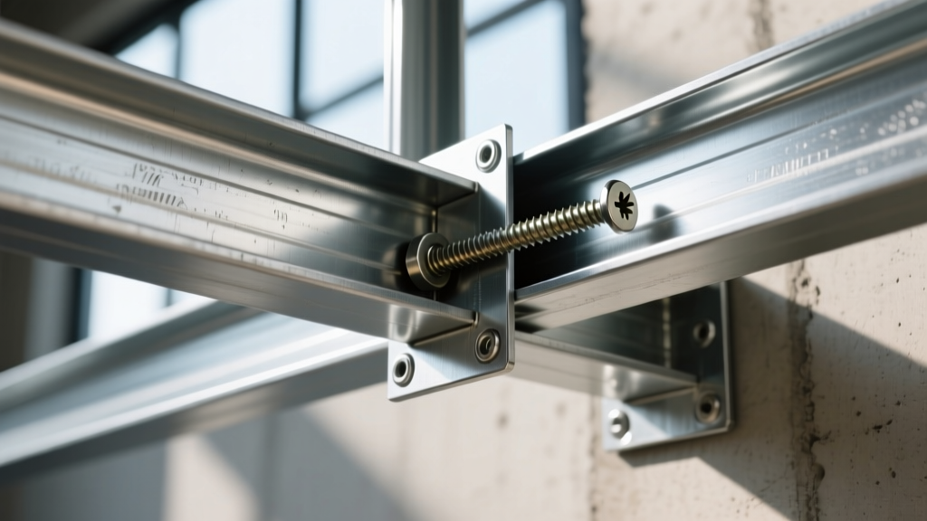
In cold-formed steel (CFS) construction, the structural integrity of a building does not rely solely on the yield strength of the studs or joists. It relies entirely on the continuous load path established by steel framing connectors. A 16-gauge structural stud capable of supporting 30,000 pounds of axial compression is rendered useless if the track connection fails at 400 pounds of shear. Selecting the right connector requires moving beyond generic catalog browsing and adopting a rigorous, vector-based decision framework that accounts for gravity, uplift, lateral shear, and environmental degradation.
The Cold-Formed Steel Engineers Institute (CFSEI) emphasizes that connection design must adhere to the AISI S100 North American Specification. This means engineers and framers must evaluate the governing failure mode: is the connection limited by the steel thickness of the connector, the bearing strength of the connected CFS members, or the pull-out/shear capacity of the fasteners? Understanding this hierarchy is the first step in our selection framework.
Connector Typology and Application Matrix
To streamline procurement and engineering approval, categorize steel framing connectors by their primary load vector and structural location. The following matrix outlines standard applications, typical industry model equivalents (such as those found in the Simpson Strong-Tie CFS catalog), and the corresponding gauge ranges.
| Connection Type | Primary Load Vector | Typical Model / Category | CFS Gauge Range | Capacity Limiting Factor |
|---|---|---|---|---|
| Joist-to-Track (Gravity) | Shear / Gravity | Lightweight Uplift/Joist Hangers (e.g., LRU, HUCQ) | 16 ga - 20 ga | Fastener shear in thin web |
| Stud-to-Track (Tension) | Uplift / Overturning | Strap Holdowns & Tension Ties (e.g., S-HD, HTT) | 12 ga - 16 ga | Strap yielding / Anchor bolt pullout |
| Truss-to-Top Track | Uplift / Lateral | Hurricane Ties / Truss Clips (e.g., H1, H2.5A equivalents) | 16 ga - 20 ga | Net section tear-out at bend |
| Deflection Track Slip | Vertical Deflection / Lateral | Slip Track Clips & S-Clips (e.g., SLD, DTC) | 16 ga - 20 ga | Lateral bracing stiffness |
| Heavy Ledger / Beam | High Shear / Gravity | Heavy Capacity Joist Hangers (e.g., HUC, HQU) | 10 ga - 12 ga | Bearing crush of CFS flange |
Managing Floor Slab Deflection with Slip Connectors
One of the most frequently misapplied categories of steel framing connectors involves deflection tracks in mid-rise and commercial construction. When CFS stud walls are placed beneath concrete floor slabs or steel beams, the floor system will deflect under live loads. If the top track is rigidly connected to both the slab and the studs, the studs will buckle under the induced axial compression.
The selection framework for deflection requires specifying bypass or slip-track connectors. These connectors allow the top track to move vertically (typically up to 1.5 inches) while transferring lateral wind and seismic loads from the studs to the primary structure. When selecting slip clips, verify the allowable lateral load capacity at the specific deflection gap. A clip rated for 800 lbs of lateral shear at a 0.5-inch gap may drop to 450 lbs at a 1.25-inch gap due to increased eccentricity and prying action on the fasteners.
Coating and Corrosion Selection Framework
Specifying the correct galvanization coating is not merely a code compliance exercise; it dictates the lifespan of the structural connection. The American Institute of Steel Construction (AISC) and building codes mandate specific coatings based on the surrounding materials and environmental exposure.
- G90 (Standard Galvanized): Features 0.90 oz/sq ft of zinc coating. This is the baseline for all interior, climate-controlled CFS framing. Do not use G90 connectors in direct contact with pressure-treated lumber or in exterior applications.
- ZMAX / G185 (Heavy Galvanized): Features 1.85 oz/sq ft of zinc. Mandatory when steel framing connectors anchor into modern pressure-treated wood sill plates. Modern preservatives like ACQ (Alkaline Copper Quaternary) and MCQ are highly corrosive to standard zinc and will consume a G90 coating in under five years.
- HDG (Hot-Dip Galvanized): Applied after fabrication, resulting in a thick, durable coating. Required for exterior exposed connections, coastal environments (within 3,000 feet of saltwater), and highly corrosive industrial interiors.
Never pair aluminum connectors with steel framing, and avoid using uncoated carbon steel screws to fasten ZMAX or HDG connectors. If the zinc coating is compromised during installation, the exposed steel will act as an anode, accelerating localized galvanic corrosion. Always use fasteners with a coating equal to or greater than the connector.
The Fastener Mismatch Failure Mode
The most common point of failure in CFS connection design is the 'weak link' phenomenon. A structural engineer may specify a heavy-duty holdown rated for 4,500 lbs of uplift. However, if the framer attaches that holdown to a 20-gauge stud using standard #10 self-drilling screws, the governing capacity of the connection drops to the pull-out strength of those specific screws in 20-gauge steel—which might only be 350 lbs per screw. The connection is now limited by the fastener, not the connector.
To resolve this, the selection framework must include fastener optimization based on drill point geometry and thread pitch:
- #1 and #2 Drill Points: Designed for thin-sheet to thin-sheet connections (e.g., 20 ga to 20 ga). Using a #3 point here will cause the screw to 'spin out' or strip the threads before the head seats, destroying the pull-out capacity.
- #3 Drill Points: The standard for structural CFS connections (e.g., 12 ga to 12 ga, or attaching connectors to 14 ga tracks). These feature a wider flute to clear chips from thicker steel.
- #4 and #5 Drill Points: Reserved for drilling through CFS into hot-rolled structural steel (W-shapes) or heavy hollow structural sections (HSS). They feature a aggressive winged tip that shears off once it penetrates the steel, allowing the threads to engage.
Real-World Edge Cases and Installation Tolerances
Catalog capacities assume perfect installation. In the field, steel framing connectors face several edge cases that degrade performance:
- Overtightening and 'Dimpling': Impact drivers set to high torque will over-spin structural screws in thin-gauge steel, creating a 'dimple' that reduces the effective bearing area and strips the internal threads. Use torque-limiting collars or depth-sensitive screw guns set to 2,500 RPM for #10 and #12 screws.
- Missed Holes and Re-drilling: If a framer misses a pre-punched hole in a joist hanger and drills a new hole adjacent to it, the net section area of the connector is reduced, and the edge distance requirement for the screw is violated. Connectors with multiple clustered holes require strict adherence to minimum edge distances (typically 1.5x the screw diameter).
- Prying Action in Uplift: When hurricane ties are installed without tight bearing against the wood or steel member, uplift forces induce prying action on the fasteners. This converts pure shear loads on the nails/screws into combined tension and shear, drastically reducing their allowable capacity.
Procurement Strategy and Cost Benchmarks
Budgeting for steel framing connectors requires looking beyond the unit cost of the hardware. While a standard 20-gauge joist hanger may cost between $2.50 and $4.50, and a heavy-duty deflection slip clip may run $8.00 to $12.00, the true cost driver is the fastener count and labor. A connector requiring sixteen #10 structural screws (at $0.25 each) adds $4.00 in fastener costs and significant labor time compared to a connector designed for pneumatic pins or powder-actuated tools (PAT).
For high-volume production framing, prioritize connectors engineered for PAT or gas-actuated pin systems where structural loads permit. For critical load-path nodes (shear walls, elevator shafts, heavy roof trusses), stick to screw-attached, high-capacity connectors, and ensure your procurement includes a 10% overage for dropped, lost, or stripped fasteners. Always demand mill certificates and ICC-ES Evaluation Reports (ESR) from your supplier to verify that the connectors meet the specific ASTM A653 coating and ASTM A1011 steel grade requirements outlined in your structural drawings.
Written by
James ThorntonJames Thornton is a construction industry veteran with 25 years of hands-on experience in wood framing, lumber grading, and residential building codes. He started as a framing carpenter in rural Oregon, earned his ICC Residential Building Inspector certification, and eventually became a senior plan reviewer for the City of Portland Bureau of Development Services. James holds a B.S. in Wood Science & Technology from Oregon State University and is a certified lumber grader through the West Coast Lumber Inspection Bureau (WCLIB). He has inspected over 3,000 residential construction sites and authored the city's internal guide on advanced framing techniques (2x6 at 24" O.C.). James lives in Bend, OR, where he builds custom timber-frame cabins and competes in lumberjack sports.
More from James Thornton
View all
Insulation
Best Home Insulation Materials: Complete 2026 Guide
Compare top home insulation materials for 2026. Find R-values, installed costs per square foot, and best uses for fiberglass, spray foam, and mineral wool.
Aug 4, 2026

Sustainable Building
Certify Your Green Building Material for LEED and WELL
Step-by-step guide to certifying a green building material for LEED v5 and WELL v2. Master EPDs, HPDs, and VOC limits for 2026 project specifications.
Aug 4, 2026

Stone & Masonry
Veneer Stacked Stone Panels: Interior Design & Style Showcase
Discover how veneer stacked stone panels transform interiors. Explore modern design profiles, material pairings, and technical installation specs.
Aug 4, 2026