Critical Light Gauge Steel Framing Details for Structural Walls
Master critical light gauge steel framing details for load-bearing walls. Explore structural connections, AISI standards, fastener specs, and bracing.

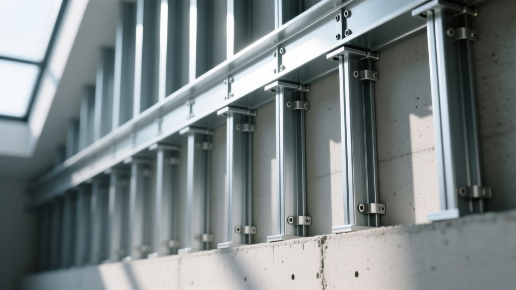
The Anatomy of Load-Bearing Light Gauge Steel Framing
When engineering load-bearing assemblies, the distinction between structural and non-structural light gauge steel framing (LGSF) is absolute. Structural studs must comply with AISI S100 and ASTM C955 standards, requiring a minimum base metal thickness of 33 mils (20 gauge) and a yield strength of 33 ksi (Grade 33) or 50 ksi (Grade 50). Non-structural studs (ASTM C645), often 25 gauge or thinner, possess no load-bearing capacity and using them in shear or axial load walls will result in catastrophic structural failure.
Decoding LGSF Nomenclature
Understanding manufacturer designations is critical for verifying structural details on-site. A standard designation like 600S162-33 breaks down as follows:
- 600: Nominal web depth in hundredths of an inch (6.00 inches).
- S: Shape identifier (S = Stud, T = Track, U = Channel, F = Furring).
- 162: Flange width in hundredths of an inch (1.625 inches).
- 33: Minimum base metal thickness in mils (0.033 inches / 20 gauge).
For multi-story commercial or residential structures, 12-gauge (97 mil) to 16-gauge (54 mil) studs with 50 ksi yield strength are standard for the lower floors to resist high axial compression and wind shear loads. The web punch-outs (service holes) must be located at the center of the stud depth and spaced to minimize shear lag, typically 24 inches on center.
Critical Connection Details and Fastener Specs
The structural integrity of an LGSF wall relies entirely on its connections. Unlike wood framing, where nails rely on friction and grain shear, steel connections depend on the shear strength of the screw and the bearing strength of the steel sheet. According to the Steel Framing Industry Association (SFIA), self-drilling screws must penetrate through the connected material and expose at least three threads beyond the outer face.
| Screw Size | Drill Point | Application | Min. Edge Distance |
|---|---|---|---|
| #8 (0.164" dia) | #2 or #3 | Light shear walls, 33-43 mil steel to steel | 1.5x diameter (0.25") |
| #10 (0.190" dia) | #3 | Standard stud-to-track, 54 mil steel | 1.5x diameter (0.28") |
| #12 (0.216" dia) | #4 or #5 | Heavy hold-downs, 68-97 mil thick steel | 1.5x diameter (0.32") |
Top and Bottom Track Anchorage
Bottom tracks in load-bearing walls must be anchored to the concrete foundation or structural slab to resist both uplift and lateral shear. The minimum requirement is a 1/2-inch diameter anchor bolt embedded at least 7 inches into the concrete, spaced at a maximum of 48 inches on center. In high-wind or seismic zones, anchor spacing is often reduced to 16 or 24 inches on center, and epoxy-set anchors are preferred over wedge anchors to prevent concrete spalling near the track edges.
Bracing and Sheathing: Preventing Racking Failure
Light gauge steel studs possess high axial compressive strength but are highly susceptible to buckling and racking under lateral loads. Structural bracing is non-negotiable. There are two primary methods for providing lateral stability:
- Structural Sheathing: Applying 7/16-inch OSB or 15/32-inch plywood to the exterior face. Sheathing must be fastened with #8 or #10 pan-head screws spaced 6 inches on center at the edges and 12 inches on center in the field. This method provides the highest shear capacity, often exceeding 800 lbs/ft depending on the aspect ratio.
- Flat Strap Bracing (Tension-Only): Installing 1.25-inch wide, 33-mil minimum galvanized steel flat straps in an 'X' pattern across the stud cavity. Strap bracing requires a structural compression strut (typically a track nested back-to-back) at the top and bottom to resist the inward buckling force generated when the tension strap engages. Straps must be tensioned using approved turnbuckles or cinching tools; loose straps provide zero lateral resistance.
Thermal Bridging and Acoustic Mitigation in Structural Walls
Steel is a highly conductive material (approximately 400 times more conductive than wood). In structural exterior walls, the steel studs act as thermal bridges, drastically reducing the effective R-value of the cavity insulation. To meet modern energy codes (like IECC 2024/2026), structural LGSF details must incorporate thermal breaks.
The most effective detail is the use of slotted web studs. These studs feature elongated cutouts in the web that lengthen the heat transfer path, reducing thermal conductivity by up to 30%. Additionally, applying a minimum of R-5 continuous rigid foam insulation (such as polyisocyanurate) over the exterior sheathing is mandatory to push the dew point outside the steel framing cavity, preventing condensation and subsequent corrosion on the interior flange.
Common Field Mistakes and Structural Failure Modes
Even with perfect engineering, poor field execution compromises LGSF assemblies. Inspectors and site supervisors must actively monitor for the following critical errors:
- Flange and Lip Cutting: Field workers frequently notch or cut the flanges and return lips of studs to run plumbing or HVAC. This destroys the stud's moment of inertia and local buckling capacity. If web penetration is required, it must only occur at pre-punched service holes. Never cut the flange.
- Screw Over-Spinning: Using high-torque impact drivers without depth-sensitive collars strips the steel threads. An over-spun screw has less than 20% of its designed pull-over and shear capacity. If a screw strips, it must be abandoned and a new screw driven at least 1 inch away.
- Missing Bridging/Blocking: For studs exceeding 10 feet in height, intermediate bracing (blocking or strap bridging) is required to prevent minor-axis buckling. Omitting this in tall commercial walls leads to severe bowing under dead loads.
- Improper Track Splicing: Top and bottom tracks must be spliced over a stud, with a minimum lap of 12 inches, fastened with a minimum of four screws. Butt-joining tracks without structural lapping creates a hinge point that fails under lateral wind loads.
Cost and Labor Metrics for Structural LGSF
Understanding the financial implications of structural light gauge steel framing details is essential for project estimating. While material costs for steel fluctuate based on global commodity markets, the precision of prefabricated LGSF panels often offsets raw material premiums through reduced labor hours.
| Cost Component | Load-Bearing LGSF (20ga/33ksi) | Load-Bearing Wood (2x6 SPF) |
|---|---|---|
| Raw Materials (Studs, Track, Fasteners) | $9.50 - $13.00 | $7.00 - $10.50 |
| Specialty Connectors (Hold-downs, clips) | $2.50 - $4.00 | $1.50 - $3.00 |
| Labor (Installation & Bracing) | $11.00 - $16.00 | $13.00 - $19.00 |
| Waste Factor | 2% - 5% (Highly recyclable) | 10% - 15% (Lumber yard offcuts) |
| Total Estimated Installed Cost | $23.00 - $33.00 / LF | $21.50 - $32.50 / LF |
While the upfront material cost for structural steel is approximately 15-20% higher than dimensional lumber, the elimination of callbacks for drywall nail pops, floor squeaks, and warping provides significant lifecycle savings. Furthermore, LGSF is impervious to termites, rot, and moisture absorption, making it the superior structural choice for high-humidity environments and multi-family residential construction where fire-rating and acoustic separation are heavily regulated.
Written by
Marcus ChenMarcus Chen is a licensed structural engineer (PE) and building materials analyst with over 12 years of experience across residential, commercial, and industrial construction. He holds a Master of Science in Civil Engineering from UC Berkeley and spent six years at Thornton Tomasetti before transitioning to independent consulting and technical writing. Marcus specializes in material selection for seismic-prone regions, concrete reinforcement strategies, and lifecycle cost analysis. His work has been cited by the American Concrete Institute (ACI) and the Structural Engineers Association of California (SEAOC). When he is not on a job site or at his desk, you will find him hiking the Sierra Nevada or restoring a 1920s craftsman bungalow in Oakland, CA.
More from Marcus Chen
View all
Construction Cost
How Much Did the Eiffel Tower Cost to Build?
How much did the Eiffel Tower cost to build in 1889? We adjust for inflation and compare its budget to modern skyscraper construction.
Aug 4, 2026
Fire Resistance
What Is a Fire Resistant Material? Testing & Certification Guide
Discover what is a fire resistant material through ASTM and UL testing. Learn how fire ratings, certifications, and assemblies work in construction.
Aug 4, 2026

Construction Cost
How Much Did the Burj Khalifa Cost to Build?
How much did the Burj Khalifa cost to build? We break down the $1.5B project and extract 5 money-saving strategies for your next build.
Jul 30, 2026