Steel Framing Building Structural Design: Load and Span Guide
Master the structural design of a steel framing building. Explore load paths, C-section spans, ASTM standards, and material costs for commercial builds.

Engineering a steel framing building requires a precise understanding of how primary and secondary structural systems interact to transfer gravity, wind, and seismic loads to the foundation. Unlike wood or concrete, steel demands rigorous attention to connection detailing, thermal bridging, and deflection limits. This guide breaks down the structural mechanics, material nomenclature, and 2026 cost metrics required to design and specify cold-formed steel (CFS) and hot-rolled systems for commercial and mid-rise applications.
Primary vs. Secondary Framing Systems
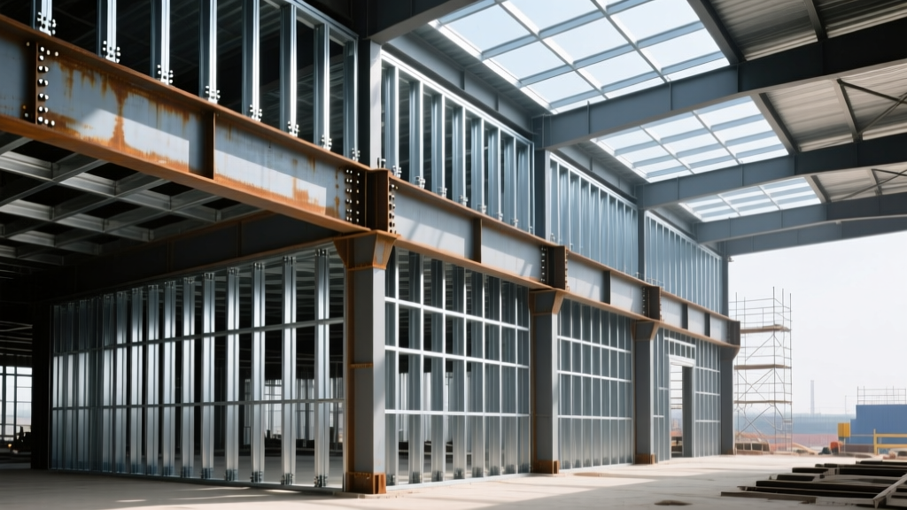
A complete steel framing building typically relies on a hybrid approach, utilizing hot-rolled structural steel for the primary skeleton and cold-formed steel (CFS) for secondary framing, shear walls, and floor decking. Selecting the right system depends on the clear-span requirements and the overall building height.
| Feature | Hot-Rolled Structural Steel (Primary) | Cold-Formed Steel / CFS (Secondary) |
|---|---|---|
| Yield Strength | 50 ksi (ASTM A992) | 33 ksi to 50 ksi (ASTM A1003) |
| Typical Applications | Main columns, long-span beams, trusses | Wall studs, floor joists, purlins, girts |
| Thickness Range | 0.25" to 4"+ (Flanges and webs) | 33 mils (20 ga) to 118 mils (10 ga) |
| Connection Method | Bolted (A325/A490) or field-welded | Self-drilling screws, pneumatic pins, welds |
Decoding Cold-Formed Steel (CFS) Nomenclature
Specifying CFS members for a steel framing building requires fluency in the standard AISI nomenclature. Misinterpreting gauge thickness or web depth is a common cause of structural deflection failures during the framing stage.
Example Designation: 800S162-54
- 800: Web depth in hundredths of an inch (8.00 inches).
- S: Member type (S = Stud, T = Track, J = Joist).
- 162: Flange width in hundredths of an inch (1.62 inches).
- 54: Minimum uncoated steel thickness in mils (54 mils / 16 gauge).
According to the Cold-Formed Steel Engineers Institute (CFSEI), structural studs and joists must utilize a minimum yield strength of 50 ksi for spans exceeding 12 feet to maintain strict L/360 live load deflection limits. For non-load-bearing partition walls, 33 ksi studs (often 33 mils / 20 gauge) are sufficient and reduce overall dead load on the primary structure.
Engineering the Lateral Load Path
Gravity loads dictate member sizing, but lateral loads (wind and seismic) dictate the building's connection topology. In a steel framing building, lateral forces are resisted through a combination of diaphragm action and shear walls.
- Roof Diaphragm Transfer: Wind pressure hits the exterior cladding and transfers to the roof deck (typically 22-gauge or 20-gauge corrugated steel). The deck acts as a deep beam, transferring shear to the perimeter bond beams via puddle welds or powder-actuated fasteners spaced at 6 inches on center.
- Strut and Drag Systems: CFS track members are doubled or tripled at the roof perimeter to act as drag struts, collecting diaphragm shear and routing it into the vertical shear walls.
- Shear Wall Resistance: Shear walls are constructed using 43-mil or 54-mil CFS studs sheathed with structural panels (OSB or plywood) or flat steel strap bracing. The Steel Framing Industry Alliance (SFIA) mandates specific hold-down anchors (e.g., Simpson Strong-Tie SSW series) at the chord studs to prevent overturning moments from lifting the wall off the foundation.
- Foundation Anchorage: Base plates and shear wall tracks are anchored to the concrete slab using ASTM F1554 Grade 36 or 55 wedge anchors, designed to resist both uplift and shear simultaneously.
Floor Joist Span Limits and Deflection Criteria
Floor vibration and deflection are the primary serviceability concerns in multi-story steel framing buildings. The industry standard limits live load deflection to L/360 and total load deflection to L/240. Below is a reference span table for 50 ksi CFS floor joists supporting a 40 psf live load and 15 psf dead load, spaced at 16 inches on center.
| Joist Designation | Thickness (Mils/Gauge) | Max Allowable Span (ft-in) | Governing Limit State |
|---|---|---|---|
| 800S162-54 | 54 mils (16 ga) | 14' - 2" | Deflection (L/360) |
| 1000S162-54 | 54 mils (16 ga) | 16' - 8" | Deflection (L/360) |
| 1000S162-68 | 68 mils (14 ga) | 19' - 4" | Bending Capacity |
| 1200S162-68 | 68 mils (14 ga) | 22' - 1" | Deflection (L/360) |
2026 Material and Erection Cost Breakdown
Budgeting for a steel framing building requires separating raw material costs from fabrication and field labor. As of early 2026, supply chain stabilization has normalized hot-rolled steel prices, though regional labor shortages continue to drive up erection costs.
| Cost Category | Unit Metric | 2026 Average Cost Range |
|---|---|---|
| Hot-Rolled Primary Steel (Material) | Per Ton | $1,150 - $1,350 |
| Hot-Rolled Fabrication & Detailing | Per Ton | $600 - $850 |
| CFS Studs & Track (Material) | Per Sq Ft of Wall Area | $1.80 - $2.60 |
| Structural Steel Erection Labor | Per Sq Ft of Footprint | $6.50 - $9.00 |
| CFS Framing Labor | Per Sq Ft of Wall Area | $3.50 - $5.50 |
Common Structural Failure Modes and Mitigation
Steel is highly predictable, but poor detailing leads to catastrophic localized failures. The American Iron and Steel Institute (AISI) design manuals highlight several critical edge cases that engineers and erectors must address.
1. Web Crippling at Bearing Points
When CFS joists rest on bearing supports without adequate stiffening, the thin web can buckle or crush under concentrated point loads.
Mitigation: Always specify web stiffeners or clip angles at bearing points for joists deeper than 8 inches, or utilize bearing-stiffener tracks that encapsulate the joist ends.
2. Torsional Buckling in Unbraced Flanges
Long, unbraced compression flanges in primary beams or deep CFS studs are prone to lateral-torsional buckling.
Mitigation: For primary beams, maintain a strict bracing interval (Lb) based on the AISC 360 specifications. For CFS wall studs, ensure gypsum sheathing or flat strap blocking is installed on both flanges at a maximum spacing of 48 inches on center to provide rotational restraint.
Steel is 400 times more conductive than wood. In a steel framing building, continuous exterior CFS studs act as thermal bridges, drastically reducing the effective R-value of cavity insulation and leading to interior condensation. Code compliance (IECC 2024/2025 updates) mandates continuous exterior rigid insulation (e.g., 2" polyiso) or specialized thermal break strips installed between the CFS stud flange and the exterior sheathing to achieve required U-factors.
3. Galvanic Corrosion at Dissimilar Metal Connections
Connecting galvanized CFS tracks directly to unprotected hot-rolled base plates or aluminum cladding in the presence of moisture triggers rapid galvanic corrosion.
Mitigation: Apply a heavy-duty bituminous coating or use EPDM isolation pads between dissimilar metals. Ensure all field-cut edges of galvanized CFS members are touched up with a zinc-rich primer (ASTM A780) before closing the wall cavities.
Written by
Priya KapoorPriya Kapoor is a real estate market analyst and construction economics researcher with expertise in housing affordability, development feasibility, and infrastructure investment. She holds a Master of Regional Planning from Cornell University and previously worked as a senior analyst at CBRE's Investment Properties group, where she modeled returns for $4B in mixed-use development pipelines. Priya now runs an independent research practice advising developers, municipalities, and REITs on construction cost forecasting and market timing. She publishes the quarterly "BuildMat Market Pulse" report tracking material price indices across 12 commodity categories. Based in Austin, TX, Priya serves on the board of Habitat for Humanity Austin and is a marathon runner.
More from Priya Kapoor
View all
Construction Cost
Cost to Build a 1600 Sq Ft Home in 2026: Full Breakdown
Accurate 2026 cost to build a 1600 sq ft home—material, labor, and regional pricing breakdowns included. Plan your budget with real-time estimates.
Aug 11, 2026
Wood & Lumber
Name the Types of Wood for Pressure Treatment and Preservation
Learn how to name the types of wood best suited for pressure treatment. Compare species treatability, chemical retention levels, and 2026 preservation costs.
Aug 4, 2026
Stone & Masonry
Stone Veneer Suppliers Lindenhurst: 2026 Cost Analysis
Analyze 2026 stone veneer costs in Lindenhurst, NY. Compare local supplier pricing, delivery fees, and Suffolk County installation labor rates.
Aug 4, 2026