Engineering Specs for Steel Building Framing Systems Explained
Comprehensive technical specifications for steel building framing systems, including ASTM standards, gauge tolerances, load capacities, and connection details.

Core Material Standards and Yield Strengths
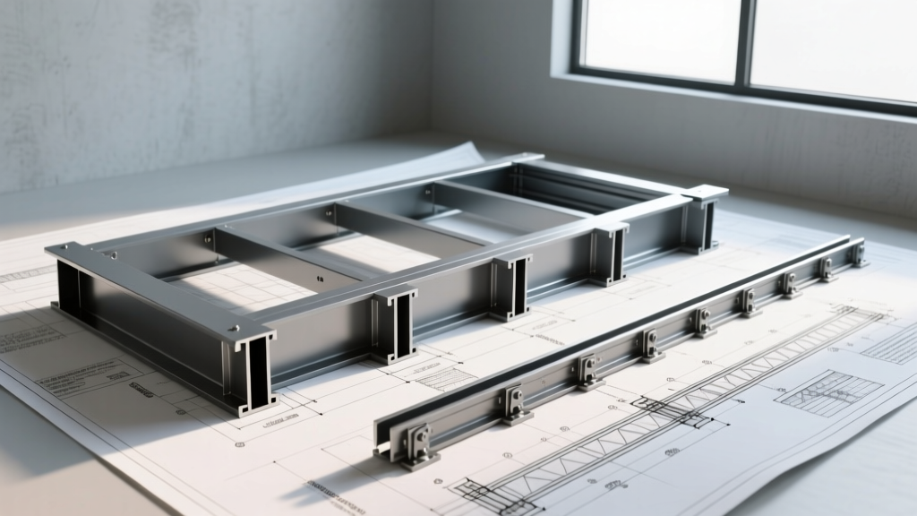
Specifying steel building framing systems requires strict adherence to metallurgical and manufacturing standards to ensure structural integrity under axial and lateral loads. For cold-formed steel (CFS) framing, the governing material standard is ASTM A1003, which dictates the requirements for carbon steel sheet used in structural framing members. Hot-rolled structural steel sections, such as wide-flange beams and heavy columns, fall under ASTM A992.
Yield strength (Fy) is the primary metric for structural capacity. Standard CFS studs and tracks are typically manufactured with a minimum yield strength of 33 ksi (kilopounds per square inch) for grades up to 18 gauge, and 50 ksi for thicker sections (16 gauge and below). In high-load or seismic applications, engineers frequently specify 80 ksi or 97 ksi high-strength steel to reduce member thickness while maintaining load capacity, thereby decreasing overall framing weight and shipping costs.
Corrosion resistance is equally critical. Galvanization levels must be specified based on environmental exposure. G60 coating (0.60 oz/sq ft of zinc) is standard for interior, climate-controlled partitions. For exterior steel building framing systems, parapets, or high-humidity zones, G90 coating (0.90 oz/sq ft) is mandatory per ASTM A653 to prevent premature section loss due to oxidation.
Dimensional Tolerances and Gauge Specifications
Never use nominal gauge numbers for structural calculations. The steel industry uses 'design thickness' for engineering math and 'minimum thickness' for manufacturing tolerances. A 16-gauge stud ordered from a roll-former must meet the minimum thickness requirement, but structural analysis must be based on the design thickness to account for the 90% manufacturing tolerance rule outlined in AISI S100.
| Nominal Gauge | Design Thickness (in.) | Min. Thickness (in.) | Weight (psf) | Primary Application |
|---|---|---|---|---|
| 12 Gauge | 0.1046 | 0.0941 | 4.26 | Heavy structural, load-bearing exterior walls |
| 14 Gauge | 0.0747 | 0.0672 | 3.05 | Standard load-bearing walls, floor joists |
| 16 Gauge | 0.0598 | 0.0538 | 2.44 | Low-rise load-bearing, non-load-bearing shafts |
| 18 Gauge | 0.0478 | 0.0430 | 1.95 | Interior non-load-bearing partitions |
| 20 Gauge | 0.0359 | 0.0323 | 1.46 | Ceiling grids, light furring, drywall backing |
Load-Bearing Capacities and Span Limits
The structural performance of steel building framing systems is governed by the American Iron and Steel Institute (AISI) S100 standard. Capacities vary drastically based on unbraced height, stud depth, and lip return dimensions.
Axial Load Limits
For a standard 6-inch wide, 16-gauge C-stud (with 1-5/8 inch flanges and 1/2 inch return lips) spaced at 16 inches on center, the allowable axial load capacity is highly dependent on the unbraced height. At an unbraced height of 10 feet, this member can typically support an axial load of approximately 14,500 lbs. However, if the unbraced height increases to 16 feet without intermediate bracing, the capacity drops to roughly 7,200 lbs due to flexural-torsional buckling. Installing flat strap blocking at mid-height restores the weak-axis bracing and nearly doubles the allowable capacity for the 16-foot wall.
Lateral and Deflection Criteria
Lateral wind and seismic loads dictate the transverse bending capacity of the framing. Deflection limits must be strictly enforced to prevent cracking in brittle finishes like gypsum board or stucco. The International Building Code (IBC) and Cold-Formed Steel Engineers Institute (CFSEI) guidelines mandate the following deflection thresholds:
- L/240: Maximum allowable deflection for live loads (wind) on exterior walls supporting brittle finishes.
- L/360: Maximum allowable deflection for total loads on interior partitions where strict finish tolerances are required.
- L/600: Required for specialized curtain wall back-up framing supporting heavy masonry or glass veneers.
Connection Hardware and Fastener Specifications
Structural connections in CFS framing rely on self-drilling screws, powder-actuated fasteners, or structural welds. The specification must detail the exact fastener diameter, head type, and penetration depth.
For structural steel-to-steel connections using self-drilling screws (per ASTM C1513), the screw must penetrate through the bottom steel sheet and extend a minimum of 3 full threads beyond the bearing surface. A #10-16 x 3/4-inch modified truss head screw is standard for 16-to-16 gauge connections, providing an allowable shear capacity of roughly 650 lbs per screw.
- #8-18 and #10-16 Self-Drillers: Used for standard stud-to-track connections and sheathing attachment. Hex washer heads (HWH) are specified for structural shear walls to prevent head pull-through under high diaphragm loads.
- Powder-Actuated Fasteners (PAFs): For anchoring bottom tracks to concrete slabs, specify Hilti X-HSN 31 or Ramset TrackFast. These pins must penetrate a minimum of 5/8 inch into normal-weight concrete (minimum 3,000 psi compressive strength) to achieve the required 250 lbs of tension capacity per anchor.
- Weld Connections: Where welding is specified over screw connections for heavy moment frames, flare-bevel groove welds or resistance spot welds must conform to AWS D1.3 (Structural Welding Code - Steel).
Thermal Bridging and Continuous Insulation Metrics
Steel is a highly conductive material (thermal conductivity of ~310 BTU-in/hr-sq ft-°F). In exterior steel building framing systems, the steel studs act as thermal bridges, severely degrading the effective R-value of the wall assembly. Ignoring this in the specification phase will result in failure to meet current 2026 ASHRAE 90.1 energy codes.
A wall cavity insulated with R-19 fiberglass batts framed with 16-gauge steel studs at 16 inches on center yields an effective cavity R-value of only R-7.1. To compensate, structural engineers and architects must specify continuous insulation (ci) on the exterior face of the framing. Adding 2 inches of polyisocyanurate rigid board (R-13 ci) outside the sheathing raises the overall assembly U-factor to code-compliant levels while keeping the dew point outside the stud cavity, thereby preventing interstitial condensation.
Specification Checklist for Structural Engineers
Before finalizing the framing package for steel building framing systems, verify the following parameters to prevent field delays and structural deficiencies:
- Verify Base Metal Thickness: Confirm that all structural calculations utilize the 'design thickness' rather than the nominal gauge or 'minimum thickness'.
- Specify Galvanization Class: Explicitly note G60 for interior dry environments and G90 for exterior, below-grade, or high-humidity exposures on all framing schedules.
- Define Bridging and Blocking: Detail the exact elevation and fastening schedule for flat strap blocking or channel bridging to ensure weak-axis bracing is achieved for axial load calculations.
- Detail Track Anchorage: Provide a specific powder-actuated fastener or wedge anchor schedule for top and bottom tracks, including edge distance requirements (minimum 3 inches from slab edges).
- Coordinate with MEP Penetrations: Specify reinforced knockouts or structural headers for studs that will be notched or cut to accommodate large HVAC ducts or plumbing chases, as cutting a flange reduces moment capacity by up to 40%.
For comprehensive load tables and span charts specific to proprietary framing profiles, structural designers should consult the American Institute of Steel Construction (AISC) design guides and the specific roll-former's ICC-ES evaluation reports.
Written by
Priya KapoorPriya Kapoor is a real estate market analyst and construction economics researcher with expertise in housing affordability, development feasibility, and infrastructure investment. She holds a Master of Regional Planning from Cornell University and previously worked as a senior analyst at CBRE's Investment Properties group, where she modeled returns for $4B in mixed-use development pipelines. Priya now runs an independent research practice advising developers, municipalities, and REITs on construction cost forecasting and market timing. She publishes the quarterly "BuildMat Market Pulse" report tracking material price indices across 12 commodity categories. Based in Austin, TX, Priya serves on the board of Habitat for Humanity Austin and is a marathon runner.
More from Priya Kapoor
View all
Construction Cost
Cost to Build a 1600 Sq Ft Home in 2026: Full Breakdown
Accurate 2026 cost to build a 1600 sq ft home—material, labor, and regional pricing breakdowns included. Plan your budget with real-time estimates.
Aug 11, 2026

Wood & Lumber
Name the Types of Wood for Pressure Treatment and Preservation
Learn how to name the types of wood best suited for pressure treatment. Compare species treatability, chemical retention levels, and 2026 preservation costs.
Aug 4, 2026
Stone & Masonry
Stone Veneer Suppliers Lindenhurst: 2026 Cost Analysis
Analyze 2026 stone veneer costs in Lindenhurst, NY. Compare local supplier pricing, delivery fees, and Suffolk County installation labor rates.
Aug 4, 2026