Steel Framing Track Specs: Gauges, Deflection, and ASTM Standards
Master steel framing track specifications, including gauge thickness, deflection limits, ASTM C645 standards, and load-bearing vs. non-load-bearing profiles.

Core Anatomy and Dimensional Specifications
The steel framing track, commonly referred to as a U-channel or runner, serves as the horizontal boundary element in cold-formed steel (CFS) framing assemblies. It caps the top and bottom of vertical studs, transferring lateral and axial loads to the primary structure. Specifying the correct track profile is not merely about matching the stud width; it requires precise alignment with structural engineering requirements, deflection tolerances, and acoustic isolation goals.
Standard track profiles are defined by their web depth (the distance between the inner flanges) and flange height. While non-structural tracks typically feature a 1-1/4-inch minimum flange height, structural load-bearing tracks require a minimum 1-5/8-inch flange to accommodate heavier fastening schedules and prevent stud pull-out under high axial loads.
Standard Dimensional Matrix
| Nominal Web Depth | Design Web Depth (in) | Min. Flange Height (in) | Available Thicknesses (mils) | Primary Application |
|---|---|---|---|---|
| 1-5/8" | 1.625 | 1.25 | 33, 43 | Non-load-bearing partitions, furring |
| 2-1/2" | 2.500 | 1.25 | 33, 43, 54 | Standard interior partitions, plumbing walls |
| 3-5/8" | 3.625 | 1.25 | 33, 43, 54, 68 | Commercial partitions, STC-rated assemblies |
| 6" | 6.000 | 1.625 | 43, 54, 68, 97 | Load-bearing exterior walls, shear walls |
| 8" | 8.000 | 1.625 | 54, 68, 97, 118 | Multi-story load-bearing, high wind zones |
| 10" | 10.000 | 1.625 | 68, 97, 118 | Heavy structural, tall parapet framing |
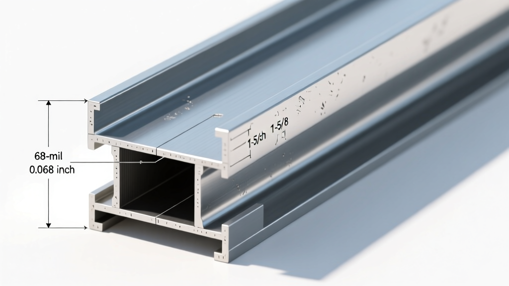
Material Standards: Base Steel vs. Design Thickness
A critical specification error in CFS framing is confusing nominal gauge with design thickness. The industry has largely abandoned the term "gauge" in favor of "mils" (thousandths of an inch) to eliminate ambiguity. According to ASTM C645, the specification for nonstructural steel framing members, thickness must be measured as the base steel thickness, exclusive of any metallic or organic coatings.
Yield strength (Fy) is equally vital. Non-load-bearing tracks (ASTM C645) typically utilize 33 ksi steel, which provides sufficient ductility for partition framing. Load-bearing tracks governed by the AISI S201 North American Standard frequently require 50 ksi steel, particularly for thicknesses of 54 mils and above, to resist crippling and buckling under concentrated roof or floor loads.
Deflection Track (Slip Track) Engineering
In multi-story commercial construction, concrete floor slabs deflect under live loads. If a standard rigid track is anchored to the slab above, this deflection will crush the vertical studs, leading to drywall cracking, popped fasteners, and compromised fire ratings. Deflection tracks (slip tracks) solve this by allowing vertical movement while maintaining lateral support.
Anatomy of a Deflection Track
- Extended Flanges: Deflection tracks feature deep flanges, typically 2 inches to 3 inches, compared to the standard 1-1/4 inches. This ensures the stud flange remains fully engaged within the track even at maximum downward deflection.
- Deflection Gap: The empty space between the top of the stud and the web of the track. Building codes and the Steel Framing Industry Association (SFIA) recommend a gap calculated based on the slab's expected deflection (usually L/360 or L/600), plus a 1/4-inch safety margin. A 3/4-inch to 1-inch gap is standard for most commercial projects.
- Bypass Clips: Used when studs do not extend into the top track. Bypass clips anchor the stud to the side of the deflection track web, utilizing slotted holes to allow the slab to move independently of the wall framing.
Fastening and Anchoring Technical Requirements
The structural integrity of the entire wall assembly relies on the track-to-structure connection. Fastener selection must account for the base material (concrete, steel deck, or wood) and the specific load vectors (shear vs. tension).
Concrete Anchoring Specifications
For bottom tracks anchored to concrete slabs, powder-actuated fasteners (PAFs) are the industry standard for non-load-bearing and light load-bearing walls. For concrete with a compressive strength exceeding 4,000 psi, a 0.300-inch diameter pin with a 1-inch embedment depth provides approximately 600 lbs of shear capacity per fastener.
For high-tension applications, such as shear wall hold-downs or uplift-resistant top tracks, wedge anchors or screw anchors are mandatory. A 1/4-inch diameter wedge anchor embedded 2 inches into 3,000 psi concrete yields an allowable tension load of approximately 800 lbs. Fastener spacing for standard bottom tracks should not exceed 24 inches on center (o.c.), while engineered shear walls often require 6-inch to 12-inch o.c. spacing at the track boundaries.
Acoustic and Fire-Rated Track Assemblies
The track is a primary vector for acoustic flanking and fire propagation. Achieving high Sound Transmission Class (STC) ratings and maintaining hourly fire-resistance ratings requires specific track treatments.
- Acoustic Isolation: To achieve STC 50 or higher, the bottom track must be isolated from the concrete slab using a 1/4-inch closed-cell neoprene or polyethylene foam tape. This breaks the mechanical vibration path. Additionally, the perimeter gap between the track and the adjacent wall must be sealed with a non-hardening, ASTM C920 compliant acoustic sealant.
- Firestop Integration: Where partition tracks intersect a fire-rated floor/celling assembly, the track must accommodate firestop materials. In head-of-wall conditions, the deflection gap must be packed with mineral wool and sealed with an intumescent firestop sealant or a pre-compressed firestop putty pad. The track flange must be wide enough to support the required depth of the mineral wool packing without compressing it beyond its tested density.
Troubleshooting Matrix: Common Specification Errors
Field failures in steel framing often trace back to incorrect track specifications during the design phase. The following matrix identifies common failure modes and their technical corrections.
| Failure Mode | Root Cause | Specification Correction |
|---|---|---|
| Stud flange tearing at track corner | Using 33-mil non-structural track for load-bearing studs; track lacks the stiffness to resist web crippling. | Upgrade to 54-mil or 68-mil structural track (AISI S201 compliant) with a minimum 1-5/8" flange height. |
| Vertical drywall cracking at ceiling line | Standard rigid track used at the top of a wall under a deflecting concrete slab; studs are being crushed. | Specify a deep-flange deflection track (slip track) with a calculated deflection gap (e.g., 1") and bypass clips. |
| Acoustic flanking (low STC scores) | Bottom track hard-mounted directly to concrete without isolation; sound transmits through the rigid connection. | Mandate 1/4" closed-cell foam tape under the bottom track and ASTM C920 acoustic sealant at all perimeter joints. |
| Track pull-out under lateral wind load | PAF pins used in low-strength or cracked concrete where tension capacity is severely compromised. | Specify adhesive anchors or screw anchors with verified tension capacities for cracked concrete per ICC-ES ESR reports. |
Final Verification Protocol
Before finalizing framing submittals, cross-reference the track schedule against the structural engineer's deflection criteria and the architect's acoustic matrix. Ensure that all load-bearing tracks specify the minimum base steel thickness and yield strength (e.g., '54 mil, 50 ksi min'), rather than relying on ambiguous nominal gauge callouts. Proper track specification eliminates costly field rework and ensures the long-term performance of the CFS assembly.
Written by
Elena RodriguezElena Rodriguez is a civil engineer and technical writer specializing in concrete technology, masonry systems, and ASTM/ACI compliance. She earned her B.S. in Civil Engineering from Texas A&M University and spent a decade at a materials testing laboratory, performing over 2,000 concrete compressive strength tests and masonry prism evaluations. Elena is an ACI-certified Field Testing Technician (Grade I) and a member of ASTM Committee C12 on Natural Building Stone. She currently consults on forensic engineering cases involving concrete failures and moisture intrusion. Based in San Antonio, TX, Elena is a proud member of the Society of Women Engineers (SWE) and coaches her daughter's FIRST Robotics team.
More from Elena Rodriguez
View all
Walls & Panels
Cost Analysis: Light Gauge Steel Framing Advantages and Disadvantages
Evaluate light gauge steel framing advantages and disadvantages through a strict cost analysis lens, comparing material, labor, and lifecycle expenses.
Aug 4, 2026
Walls & Panels
Gypsum Board Types: Exact Specifications, Thickness & Dimensions
Compare standard, Type X, and moisture-resistant gypsum board types. Get exact specifications, thicknesses, dimensions, and ASTM standards for your project.
Aug 4, 2026
Fire Resistance
Best Fire-Resistant Outdoor Decking Materials: 2026 Buyer Guide
Discover the best fire-resistant outdoor decking materials for 2026. Compare Class A PVC, aluminum, and hardwood options for WUI compliance and safety.
Aug 4, 2026