Types of Wooden Trusses: Installation Best Practices & Specs
Master the installation of various types of wooden trusses. Learn TPI bracing specs, hardware selection, bearing tolerances, and cost baselines.

Bearing Surface and Top Plate Tolerances
The structural integrity of any truss system begins at the bearing point. Before the first truss is lifted, the top plate of the supporting wall must be verified for level and alignment. According to standards published by the Truss Plate Institute (TPI), the top plate must not deviate more than 1/4 inch from a straight line over any 10-foot span, and the total deviation across the entire bearing length must not exceed 1/2 inch.
When dealing with different types of wooden trusses, bearing length requirements vary based on the load and span. Standard residential trusses (spans up to 30 feet) require a minimum bearing length of 3 inches on wood or steel. Heavy-load trusses, such as attic trusses designed for habitable space or floor trusses, require a minimum 5-inch bearing surface. If shimming is necessary to correct plate elevation, do not use compressible materials like cedar shingles or asphalt shingles. Use structural-grade, full-width steel plates or treated hardwood shims spanning the entire width of the top plate to prevent point-loading and localized crushing of the top chord.
Hardware Selection by Types of Wooden Trusses
Connector selection is not one-size-fits-all. The uplift and lateral shear forces dictate the specific hurricane ties and straps required. For precise load ratings and nail schedules, always cross-reference the engineered truss design drawings with the Simpson Strong-Tie truss connector catalog. Below is a baseline matrix for standard residential applications.
| Truss Type | Primary Application | Recommended Heel Connector | Minimum Fastener Schedule (Per Connector) |
|---|---|---|---|
| Fink / W-Truss | Standard pitched roofs (4/12 to 12/12) | H2.5A (18-gauge) | (8) 10d x 1.5" nails to truss; (4) 10d to plate |
| King Post / Queen Post | Short spans, aesthetic exposed trusses | H5 (14-gauge) or LSTA Strap | (10) 10d x 1.5" nails to truss; (6) 16d to plate |
| Scissor Truss | Vaulted ceilings (bottom chord slope ≥ 2/12) | H2.5A or H5 (depending on uplift) | (8) 10d x 1.5" nails; slot one side for horizontal movement |
| Attic Truss | Habitable roof space, heavy floor loads | H5 or custom engineered holdowns | (12) 16d nails; requires continuous structural rim board |
Note on Scissor Trusses: Because the bottom chord of a scissor truss slopes, it induces horizontal thrust at the bearing points. One side of the truss must be attached using a slotted connector (like the Simpson H2.5A with the slot oriented horizontally) or a specialized sliding clip to allow for thermal expansion and deflection without pushing the exterior walls outward.
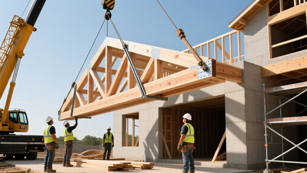
Erection Sequence and Temporary Bracing Protocol
Temporary bracing is the most frequently neglected phase of truss installation, resulting in the majority of jobsite collapses during the framing stage. The Building Component Safety Information (BSI-B10) guidelines mandate a strict erection sequence.
- First Truss Stabilization: The first truss must be set, plumbed, and immediately secured with ground-to-truss diagonal braces (typically 2x4s nailed to stakes driven into the soil or secured to the floor deck). Use at least two braces on each side of the first truss.
- Sequential Setting and Top Chord Bracing: As subsequent trusses are set, install continuous lateral bracing (CLB) along the top chords. Use 1x4 or 2x4 lumber nailed to the top chord of every truss with two 8d nails per intersection. This prevents the trusses from buckling laterally under wind loads before the roof sheathing is applied.
- Bottom Chord Bracing: For spans exceeding 25 feet, install temporary 1x4 lateral bracing along the bottom chords to prevent upward bowing during sheathing operations.
- Diagonal Web Bracing: Install temporary 1x6 or 2x4 diagonal braces crossing the webs at approximately 45-degree angles. These must be installed in an 'X' pattern every 25 to 35 feet along the length of the building to prevent domino-effect collapse.
Permanent Lateral and Diagonal Bracing Requirements
Once the roof is sheathed, the sheathing acts as the permanent diaphragm for the top chords. However, the web members and bottom chords still require permanent bracing as specified by the truss engineer. The American Wood Council (AWC) National Design Specification outlines the necessity of these members to reduce the unbraced length of compression members.
Lateral Bracing (LBR)
Permanent continuous lateral bracing must be installed on any web or bottom chord designated on the truss design drawing. The maximum spacing for permanent lateral bracing is typically 10 feet for top chords (often satisfied by sheathing) and 10 feet for webs and bottom chords. The bracing material must be a minimum 2x4, nailed to each intersecting member with two 16d nails.
Diagonal Bracing (DBR)
Permanent diagonal bracing is required to transfer lateral forces from the truss system to the supporting walls. It must be installed in the plane of the top and bottom chords, crossing the trusses at a 45-degree angle (between 30 and 60 degrees is acceptable). DBR must be installed every 20 feet for buildings in low-wind zones, and every 10 to 15 feet in high-wind or seismic zones. Ensure the DBR is fastened to the top plate or a structural blocking member at the bearing walls to complete the load path.
"Over 80% of truss failures during construction occur because the contractor relied on the roof sheathing to provide permanent stability before it was fully nailed, or completely omitted the permanent diagonal bracing specified on the engineering drawings." — Structural Forensics Review, Wood Framing Institute.
Common Installation Failures and Troubleshooting
Identifying deviations early prevents costly tear-outs and structural deficiencies. Use this diagnostic matrix to address common field issues.
| Observed Symptom | Root Cause | Required Field Correction |
|---|---|---|
| Bottom chord bowing upward between panel points | Missing permanent lateral bracing or spacing exceeds 10 ft. | Install 2x4 continuous lateral bracing (CLB) perpendicular to the bottom chord, nailed with (2) 16d nails per truss. |
| Exterior walls bowing outward after truss set | Scissor trusses installed with rigid connectors on both sides; no horizontal slip joint. | Remove connector on one side of each scissor truss. Replace with slotted H2.5A clip to allow horizontal deflection. |
| Truss webs split near metal connector plates | Improper crane rigging; lifting from a single panel point instead of a spreader beam. | Consult truss engineer. Sister a 2x4 or 2x6 web member alongside the split web, bolted with 1/2" carriage bolts. |
| Gable end truss leaning or out of plumb | Inadequate gable end bracing; reliance on fascia board for lateral support. | Install 2x4 T-braces from the gable truss to the interior trusses at 24" on center, or frame a structural gable end wall. |
2026 Labor and Material Cost Baselines
Accurate budgeting requires separating the truss package costs from the specialized labor and equipment required for erection. In 2026, while lumber volatility has largely stabilized compared to the early 2020s, crane operation and specialized framing labor remain premium cost centers.
| Cost Category | Unit / Metric | 2026 Estimated Range (USD) |
|---|---|---|
| Standard Fink Truss Package | Per square foot of roof area | $4.50 - $7.20 |
| Attic / Floor Truss Package | Per square foot of roof area | $9.00 - $14.50 |
| Mobile Crane Rental (with operator) | Per hour (4-hour minimum) | $160 - $240 |
| Truss Setting Labor (Crew of 4) | Per square foot of footprint | $2.50 - $4.00 |
| Permanent Bracing Materials & Labor | Per lineal foot of bracing | $3.50 - $5.50 |
When calculating total installation costs, factor in a 10% waste and hardware overage for hurricane ties, LSTA straps, and bracing lumber. Always require the truss manufacturer to provide a site-specific erection manual and the BCSI-B10 summary sheet, which must be kept on-site for the duration of the framing phase to ensure compliance with local building inspections.
Written by
James ThorntonJames Thornton is a construction industry veteran with 25 years of hands-on experience in wood framing, lumber grading, and residential building codes. He started as a framing carpenter in rural Oregon, earned his ICC Residential Building Inspector certification, and eventually became a senior plan reviewer for the City of Portland Bureau of Development Services. James holds a B.S. in Wood Science & Technology from Oregon State University and is a certified lumber grader through the West Coast Lumber Inspection Bureau (WCLIB). He has inspected over 3,000 residential construction sites and authored the city's internal guide on advanced framing techniques (2x6 at 24" O.C.). James lives in Bend, OR, where he builds custom timber-frame cabins and competes in lumberjack sports.
More from James Thornton
View all
Insulation
Best Home Insulation Materials: Complete 2026 Guide
Compare top home insulation materials for 2026. Find R-values, installed costs per square foot, and best uses for fiberglass, spray foam, and mineral wool.
Aug 4, 2026

Sustainable Building
Certify Your Green Building Material for LEED and WELL
Step-by-step guide to certifying a green building material for LEED v5 and WELL v2. Master EPDs, HPDs, and VOC limits for 2026 project specifications.
Aug 4, 2026

Stone & Masonry
Veneer Stacked Stone Panels: Interior Design & Style Showcase
Discover how veneer stacked stone panels transform interiors. Explore modern design profiles, material pairings, and technical installation specs.
Aug 4, 2026