Concrete Expansion Joint vs Control Joint: Mix Design & Spacing Guide
Master the concrete expansion joint vs control joint debate. Learn how mix design, shrinkage rates, and ACI spacing rules dictate slab joint layouts.

The Core Difference: Shrinkage vs. Thermal Movement
The phrase 'concrete expansion joint vs control joint' is frequently misused in construction. To specify the correct jointing strategy, engineers and contractors must distinguish between volumetric shrinkage during the curing process and thermal expansion during the slab's service life. Misidentifying these forces leads to random cracking, spalling, or structural buckling.
Quick Definition Matrix
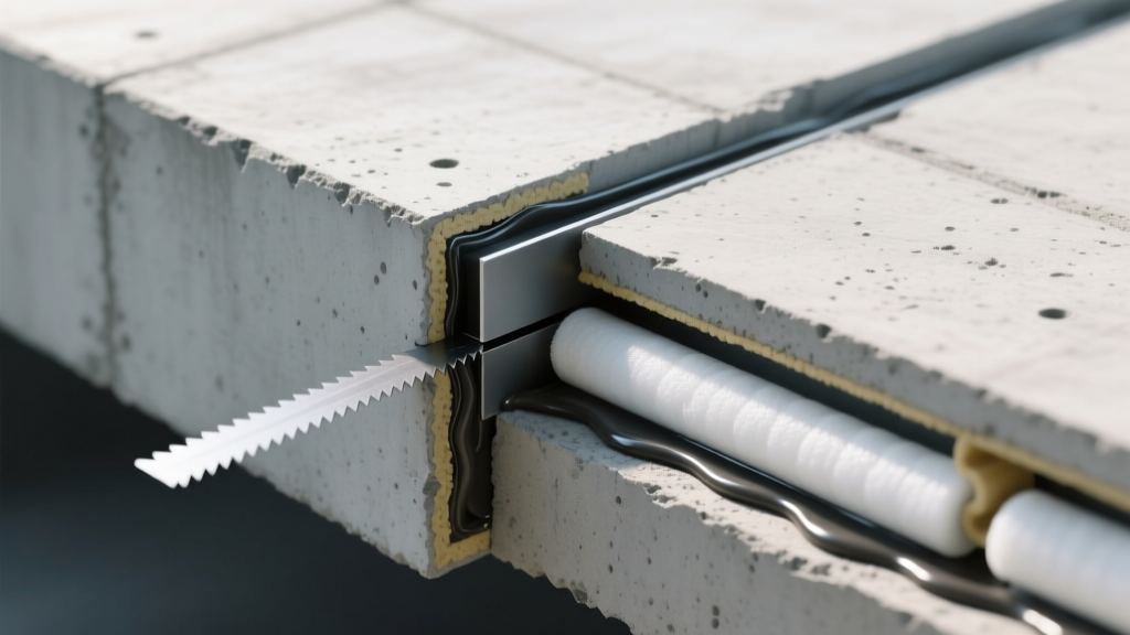
- Control Joints (Contraction Joints): Intentional, continuous planes of weakness created by sawing, tooling, or forming. They do not allow for expansion; they force the concrete to crack in a straight, hidden line as it shrinks during hydration and drying.
- Expansion Joints (Isolation Joints): Full-depth physical separations filled with compressible material. They isolate the slab from adjacent structures (walls, columns, curbs) or separate massive expanses of concrete to accommodate thermal growth and prevent compressive crushing.
How Concrete Mix Design Dictates Joint Strategy
Joint layout is not arbitrary; it is a direct response to the concrete's mix design. The proportions of water, cement, and aggregate determine both the drying shrinkage potential and the coefficient of thermal expansion (CTE).
Water-Cement Ratio and Shrinkage
Drying shrinkage is the primary driver for control joint spacing. According to the American Concrete Institute (ACI 302.1R), the water-to-cement (w/c) ratio is the most critical variable. A mix with a w/c ratio above 0.50 experiences significantly higher volumetric shrinkage than a low-water mix (w/c < 0.45).
For high-shrinkage mixes, control joints must be spaced closer together—typically 24 times the slab thickness. For low-shrinkage mixes utilizing supplementary cementitious materials (SCMs) like slag cement or Class F fly ash, spacing can safely extend to 30 or 36 times the slab thickness. For a standard 4-inch residential slab, this means reducing joint spacing from 12 feet down to 8 feet if the w/c ratio exceeds 0.50.
Aggregate Selection and Thermal Coefficients
While control joints manage shrinkage, expansion joints manage thermal movement. The CTE of concrete is heavily influenced by the coarse aggregate, which makes up 60-75% of the mix volume. Quartzite and sandstone aggregates exhibit high thermal expansion (up to 7.5 x 10^-6 per °F), requiring wider expansion joints and more frequent isolation from fixed structures. Conversely, limestone and basalt aggregates have lower CTEs (around 3.0 x 10^-6 per °F), allowing for longer continuous pours before an expansion joint is mandated. Refer to the Portland Cement Association's guidelines on concrete cracking for detailed aggregate CTE data.
Control Joints: Sizing, Spacing, and Saw-Cut Timing
A control joint is only effective if it is deep enough to weaken the slab cross-section and cut at the exact right moment in the hydration cycle.
The Depth Rule
Standard industry practice dictates that saw-cut control joints must be 1/4 to 1/3 the depth of the slab. For a 4-inch slab, the cut must be exactly 1 inch to 1.33 inches deep. Cutting too shallow results in random cracking outside the joint; cutting too deep compromises the slab's aggregate interlock and shear transfer capacity.
The 6-to-18 Hour Saw-Cut Window
Timing is the most common point of failure in control joint execution. Conventional abrasive saws must cut within 6 to 18 hours after finishing, depending on ambient temperature and mix set times. If the crew waits too long, internal tensile stresses exceed the concrete's tensile strength, and random cracking occurs before the saw blade touches the surface.
Early-Entry Alternative: Using early-entry dry-cut saws (e.g., Soff-Cut technology) allows contractors to cut joints within 1 to 4 hours of finishing, while the concrete is still in its 'green' state. This requires specialized blades with a specific skid plate design to prevent raveling at the joint edges.
| Slab Thickness | Max Spacing (Low Shrinkage Mix) | Max Spacing (High Shrinkage Mix) | Required Cut Depth |
|---|---|---|---|
| 4 inches | 12 feet (36x) | 8 to 10 feet (24x-30x) | 1.0 - 1.33 inches |
| 6 inches | 15 to 18 feet | 12 feet | 1.5 - 2.0 inches |
| 8 inches | 20 to 24 feet | 16 feet | 2.0 - 2.66 inches |
Expansion Joints: Isolation and Structural Separation
Unlike control joints, expansion joints must penetrate the entire depth of the slab and include a compressible filler to prevent the extrusion of incompressible materials (like gravel or hardened concrete spalls) into the gap, which would cause spalling under compressive thermal loads.
Specifying the Right Filler Material
The Federal Highway Administration (FHWA) outlines strict material requirements for joint fillers in heavy-duty and commercial applications. Select the filler based on the specific ASTM standard required for the project:
- ASTM D1751 (Preformed Cork): Traditional, highly compressible, but susceptible to moisture degradation if left exposed. Best for interior slabs or areas receiving a thick sealant cap.
- ASTM D1752 (Sponge Rubber / Closed-Cell Foam): The modern standard for exterior and commercial slabs. Products like W.R. Meadows FIBRE EXPANSION JOINT or closed-cell polyethylene backer rods (e.g., Sika Backer Rod) offer excellent recovery after compression and do not absorb water.
- ASTM D994 (Asphalt-Impregnated Fiberboard): A cost-effective option for standard flatwork, though it can become brittle over time and lacks the elastic recovery of closed-cell foams.
Warning: The Backer Rod Sizing Rule
When sealing an expansion joint with a polyurethane or silicone sealant (like SikaFlex-1A or W.R. Meadows Deck-o-Seal), always use a closed-cell backer rod that is 25% larger than the joint width. For a 1/2-inch joint, use a 5/8-inch backer rod. This ensures a tight friction fit and creates the required 'hourglass' shape in the sealant, allowing it to stretch without tearing away from the concrete bond line.
Cost Breakdown: Forming vs. Sawing vs. Fillers
Budgeting for jointing requires understanding the labor and material differences between control and expansion joints. The following estimates reflect 2026 commercial and residential pricing averages.
| Joint Type | Installation Method | Material Cost (per LF) | Labor Cost (per LF) | Total Estimate |
|---|---|---|---|---|
| Control Joint | Early-Entry Soff-Cut | $0.05 (blade wear) | $0.75 - $1.25 | $0.80 - $1.30 |
| Control Joint | Pre-pour PVC Bulkhead | $0.20 - $0.40 | $1.50 - $2.50 | $1.70 - $2.90 |
| Expansion Joint | 1/2" Closed-Cell + Sealant | $1.80 - $3.00 | $2.50 - $4.00 | $4.30 - $7.00 |
Common Failure Modes and Troubleshooting
Even with perfect mix design, execution errors lead to joint failure. Recognize these edge cases to prevent costly slab replacements.
1. Control Joint Raveling and Spalling
Symptom: The edges of the saw-cut crumble, leaving a jagged, wide groove that collects debris.
Cause: Sawing too early with conventional equipment, or using a dull diamond blade on hard aggregate (like quartzite).
Fix: Switch to early-entry dry-cut saws with specialized skid plates, or delay conventional sawing until the concrete achieves sufficient surface strength (typically 12+ hours in cool weather). Always match the diamond blade bond to the aggregate hardness.
2. Expansion Joint Extrusion (Blowouts)
Symptom: The sealant and backer rod are pushed upward out of the joint during hot weather, creating a tripping hazard.
Cause: The joint was not cleaned of dust and slurry before sealant application, causing adhesive failure. Alternatively, the backer rod was punctured during installation, allowing sealant to bond to the bottom of the joint (three-sided adhesion), which restricts movement and forces the material upward.
Fix: Always use a high-pressure air compressor to clean joints. Apply a bond-breaker tape to the bottom of the expansion joint if a backer rod is not used, ensuring the sealant only bonds to the two vertical sides (two-sided adhesion).
3. Random Cracking Between Control Joints
Symptom: Diagonal or transverse cracks appear in the middle of the slab panels, ignoring the saw-cuts.
Cause: The panel aspect ratio exceeds 1.5 to 1 (e.g., a joint layout creating 10-foot by 16-foot rectangles), or the subgrade was unevenly compacted, causing differential settlement.
Fix: Maintain square or near-square panel geometries. For a 10-foot width, the length should not exceed 15 feet. Ensure subgrade compaction meets 95% Proctor density before pouring.
Written by
Marcus ChenMarcus Chen is a licensed structural engineer (PE) and building materials analyst with over 12 years of experience across residential, commercial, and industrial construction. He holds a Master of Science in Civil Engineering from UC Berkeley and spent six years at Thornton Tomasetti before transitioning to independent consulting and technical writing. Marcus specializes in material selection for seismic-prone regions, concrete reinforcement strategies, and lifecycle cost analysis. His work has been cited by the American Concrete Institute (ACI) and the Structural Engineers Association of California (SEAOC). When he is not on a job site or at his desk, you will find him hiking the Sierra Nevada or restoring a 1920s craftsman bungalow in Oakland, CA.
More from Marcus Chen
View all
Construction Cost
How Much Did the Eiffel Tower Cost to Build?
How much did the Eiffel Tower cost to build in 1889? We adjust for inflation and compare its budget to modern skyscraper construction.
Aug 4, 2026
Fire Resistance
What Is a Fire Resistant Material? Testing & Certification Guide
Discover what is a fire resistant material through ASTM and UL testing. Learn how fire ratings, certifications, and assemblies work in construction.
Aug 4, 2026

Construction Cost
How Much Did the Burj Khalifa Cost to Build?
How much did the Burj Khalifa cost to build? We break down the $1.5B project and extract 5 money-saving strategies for your next build.
Jul 30, 2026