Fiber Mesh vs Wire Mesh in Concrete: Troubleshooting Slab Cracks
Diagnose and repair slab cracking by understanding fiber mesh vs wire mesh in concrete. Learn failure modes, structural limits, and epoxy fixes.

Diagnosing the Root Cause: Reinforcement Failures in Concrete Slabs
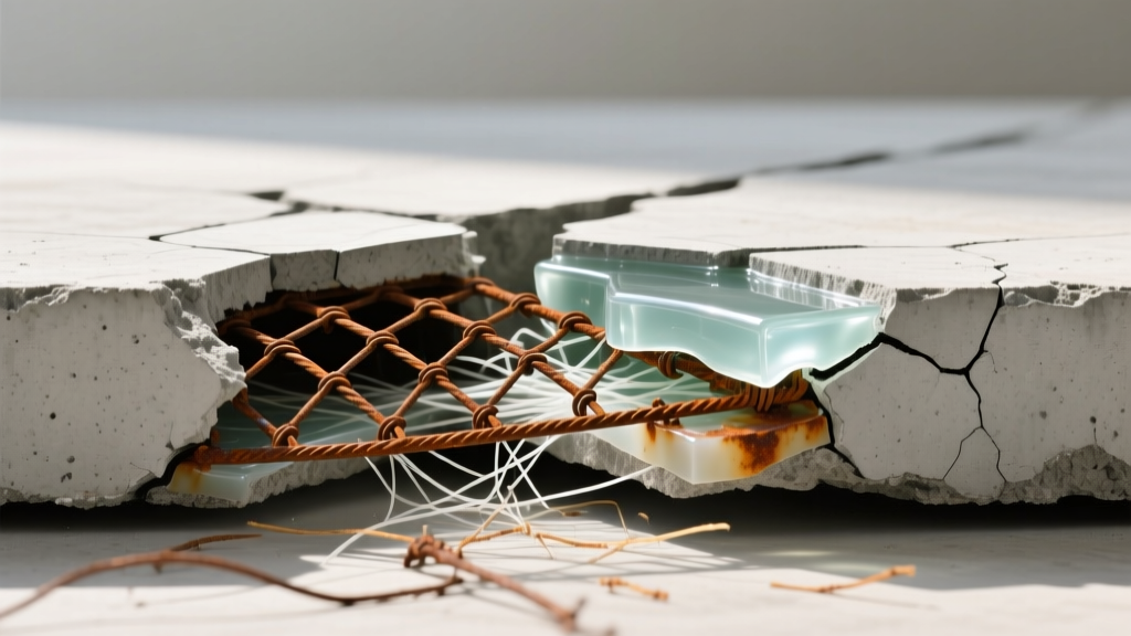
When a concrete slab cracks, spalls, or deflects, the immediate instinct is to blame the subgrade or the mix design. However, a vast majority of premature slab failures stem from a fundamental misunderstanding of reinforcement mechanics—specifically, the misapplication of fiber mesh vs wire mesh in concrete. Troubleshooting these failures requires moving beyond surface-level patching and identifying whether the installed reinforcement was structurally inadequate, improperly positioned, or incorrectly specified for the applied loads.
According to guidelines published by the American Concrete Institute (ACI), reinforcement does not prevent concrete from cracking; it controls crack width and maintains structural integrity after cracking occurs. When diagnosing a failed slab, the first step is determining whether the specification called for secondary reinforcement (plastic shrinkage control) or primary reinforcement (structural load transfer), and whether the executed pour matched that design.
The Tensile Zone Misconception
Concrete is exceptionally strong in compression but weak in tension. As a slab cures and experiences thermal contraction or subgrade settlement, tensile stresses develop. If the reinforcement is not located in the tensile zone (the top third of the slab for shrinkage, or the bottom third for mid-span bending under load), it provides zero structural benefit. Troubleshooting begins by extracting core samples to locate the exact depth of the wire mesh or the distribution density of the fiber mesh.
Troubleshooting Fiber-Reinforced Slab Failures
Fiber reinforcement is frequently misunderstood as a universal replacement for steel. In reality, fibers are categorized by material and size, each serving a distinctly different mechanical purpose. Misdiagnosing the fiber type leads to improper repair strategies.
Contractors often use the term "fiber mesh" generically. Micro-synthetic fibers (polypropylene) and macro-synthetic fibers (polyolefin) perform entirely different functions. Assuming a slab with micro-fibers has structural capacity is a critical troubleshooting error that leads to catastrophic overlay failures.
Failure Mode 1: Micro-Synthetic Over-Reliance
The Symptom: Wide, structural cracks exceeding 0.015 inches, often accompanied by vertical displacement (faulting) at joints.
The Cause: Micro-synthetic fibers are dosed at 0.5 to 1.5 lbs per cubic yard. Their sole purpose is to interrupt plastic shrinkage cracking during the first 24 hours of hydration. They possess no structural tensile capacity. If a slab subject to heavy forklift traffic or expansive subgrade soils was poured with only micro-fibers, the slab lacks the post-crack flexural strength required to hold the panels together.
The Repair: Routing and sealing is insufficient here, as the cracks will continue to widen under load. You must restore structural continuity using high-modulus epoxy injection (e.g., 100% solids, low-viscosity epoxy meeting ASTM C881 Type I). For joints that have faulted, install cross-stitching using #4 rebar drilled and epoxied at 45-degree angles across the crack before injecting.
Failure Mode 2: Macro-Fiber Balling and Shadow Cracking
The Symptom: Localized surface spalling, exposed fiber clumps, and "shadow" cracking radiating from aggregate clusters.
The Cause: Macro-synthetic fibers (dosed at 3 to 7 lbs per cubic yard) are designed to replace light-gauge wire mesh by providing residual flexural strength (measured via ASTM C1609). However, if added to the mixer too quickly or without adequate slump management, the fibers "ball" or clump together. This creates voids in the matrix and leaves other areas entirely unreinforced.
The Repair: Surface spalling caused by fiber balls requires partial-depth patching. Saw-cut the perimeter of the spalled area, chip down to sound concrete (minimum 1/2 inch depth), and apply a polymer-modified cementitious patching compound. Do not use standard sand mixes, as they lack the bond strength required for thin-edge feathering.
Troubleshooting Welded Wire Mesh (WWF) Failures
Welded Wire Fabric (typically 6x6 W1.4xW1.4 for residential and light commercial) is the traditional standard for shrinkage and temperature reinforcement. However, its rigid nature makes it highly susceptible to installation errors that compromise its structural utility.
Failure Mode 1: Mesh Depressing During the Pour
The Symptom: A network of fine, map-like shrinkage cracks across the entire slab surface, despite the presence of wire mesh.
The Cause: This is the most common installation failure in the industry. If the wire mesh is laid flat on the subgrade and concrete is dumped directly onto it, the weight of the screed and the concrete pushes the mesh to the very bottom of the slab. Shrinkage cracks initiate at the surface and propagate downward. Mesh located at the bottom of the slab cannot intersect these surface cracks, rendering it useless for shrinkage control.
The Repair: Since the cracks are non-structural shrinkage cracks, structural epoxy is overkill. Use a high-build, semi-rigid polyurethane joint filler or a methyl methacrylate (MMA) resin for rapid-cure cosmetic repairs. To prevent water infiltration and subgrade erosion, route the cracks to a 1/4-inch width and fill with a self-leveling polyurethane sealant.
Failure Mode 2: Corrosion-Induced Spalling
The Symptom: Delamination, rust-stained pop-outs, and linear cracking directly mirroring the grid pattern of the wire mesh.
The Cause: Insufficient concrete cover over the mesh, combined with chloride ingress (from deicing salts or marine environments). As the steel corrodes, iron oxide expands up to seven times its original volume, generating internal tensile stresses that blow the concrete cover off the top of the mesh.
The Repair: Remove all spalled concrete and mechanically clean the rusted wire mesh. If the wire cross-section has lost more than 20% of its diameter, cut out the corroded section and tie in new epoxy-coated wire mesh. Apply a zinc-rich primer to the exposed steel, then patch with a shrinkage-compensated, polymer-modified repair mortar containing a migrating corrosion inhibitor (MCI).
Repair Matrix: Matching the Crack to the Mesh and the Fix
Use the following diagnostic matrix to determine the appropriate repair methodology based on the installed reinforcement and the observed failure mode.
| Reinforcement Type | Observed Failure Mode | Root Cause | Required Repair Protocol |
|---|---|---|---|
| Micro-Synthetic Fiber | Wide structural cracks (>1/8") | Spec error: Used for structural loads | Cross-stitching + Epoxy Injection |
| Macro-Synthetic Fiber | Surface spalling / clumps | Fiber balling during batching | Partial-depth polymer patching |
| Welded Wire Mesh (WWF) | Surface map-cracking | Mesh pushed to bottom of slab | Routing + Polyurethane sealant |
| Welded Wire Mesh (WWF) | Linear rust-stained cracking | Corrosion due to low cover | Mesh replacement + MCI mortar |
Retrofitting and Overlay Decision Framework
When a slab has suffered extensive failure due to the wrong choice between fiber mesh vs wire mesh in concrete, surface repairs are merely cosmetic. A structural overlay is required. The National Ready Mixed Concrete Association (NRMCA) emphasizes that overlay performance is entirely dependent on the bond to the existing substrate and the reinforcement chosen for the new wearing course.
Step 1: Core Sampling and GPR Scanning
Before specifying an overlay, extract 2-inch diameter core samples to determine the existing slab thickness, compressive strength, and the exact location of the original wire mesh. Use Ground Penetrating Radar (GPR) to map the continuous layout of the buried mesh. If the existing mesh is heavily corroded or located at the very bottom of a thin slab (< 3 inches), the existing slab cannot serve as a reliable structural base.
Step 2: Selecting the Overlay Reinforcement
For bonded overlays (1.5 to 3 inches thick), wire mesh is highly impractical. It is nearly impossible to maintain the correct vertical positioning of wire mesh in a thin overlay pour; it will inevitably be pushed to the bottom, resting directly on the bond-breaker or existing slab.
"For thin bonded overlays, macro-synthetic fibers dosed at 5 to 7 lbs per cubic yard provide superior 3-dimensional reinforcement. They eliminate the risk of misplacement inherent to wire mesh and significantly reduce the curling and warping that cause overlay delamination."
If the overlay is unbonded (separated by a polyethylene slip sheet) and exceeds 4 inches in thickness, macro-synthetic fibers can still be utilized, provided the subgrade is uniformly compacted to prevent differential settlement. For heavy industrial overlays subject to point loads, traditional rebar (#3 or #4) on chairs is required, as neither fibers nor standard WWF provide the necessary flexural capacity for extreme point loads over soft subgrades.
Preventative Specifications for Future Pours
The data from the Portland Cement Association (PCA) confirms that the vast majority of reinforcement failures are specification and execution errors, not material defects. To prevent future troubleshooting:
- Specify by Performance, Not Material: Instead of writing "add fiber mesh" to the mix design, specify the required residual strength (e.g., "Provide macro-synthetic fibers to achieve a minimum residual strength of 150 psi at L/600 deflection per ASTM C1609").
- Mandate Mesh Elevation: For WWF, explicitly require the use of concrete dobies (chairs) to hold the mesh in the upper third of the slab, and prohibit the practice of "pulling up" the mesh during the pour, which creates uneven coverage and trips hazards.
- Control the Slump: High-slump concrete (>5 inches) exacerbates wire mesh depression and causes macro-fibers to clump. Limit slump to 4 inches and use water-reducing admixtures (WRAs) to maintain workability without adding water.
Written by
David NakamuraDavid Nakamura is a licensed architect (AIA) and construction technology writer focused on sustainable building methods, mass timber engineering, and high-performance building envelopes. He holds a Master of Architecture from the University of Washington and is a certified Passive House Consultant (CPHC). David spent eight years at the Seattle firm Mithun, where he led the design of three LEED Platinum projects, before founding his own practice specializing in net-zero residential design. He serves on the editorial advisory board of GreenBuilder Magazine and has authored peer-reviewed papers on cross-laminated timber (CLT) connections for the Journal of Structural Engineering. In his spare time, David teaches woodworking at Pratt Fine Arts Center and kayaks the Puget Sound.
More from David Nakamura
View all
Construction Cost
Labor Cost to Build a Deck Per Sq Ft: 2026 Installation Guide
Discover the exact labor cost to build a deck per sq ft in 2026. This installation guide breaks down contractor rates, complexity factors, and hidden fees.
Aug 4, 2026

Construction Cost
How Much Does It Cost to Build a 3 Bedroom House? Financing Guide
Learn exactly how much it costs to build a 3 bedroom house and explore 2026 financing options, construction loan types, and budget frameworks for your build.
Aug 4, 2026
Construction Cost
Cost to Build a Tennis Court: 2026 Guide
How much does it cost to build a tennis court in 2026? Breakdowns for asphalt, concrete, and synthetic surfaces plus fencing and lighting.
Jul 30, 2026