7 Types of Cracks in Concrete Linked to Mix Design Flaws
Discover how mix design flaws cause 7 types of cracks in concrete. Learn to identify plastic shrinkage, thermal, and ASR cracks and engineer fixes.

The Batch Plant Blueprint: Why Mix Design Dictates Crack Formation
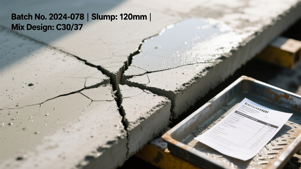
Concrete cracking is frequently blamed on the finishing crew, ambient weather, or inadequate curing. However, when forensic engineers analyze the types of cracks in concrete, the root cause often traces back to the batch plant. A poorly proportioned mix design guarantees volumetric instability, regardless of how perfectly a slab is struck off or troweled. While some cracking is inevitable due to concrete's inherent tensile weakness, catastrophic or premature cracking is almost always a symptom of chemical or physical imbalances in the mix.
Understanding the relationship between mix constituents and crack morphology allows QA managers and structural engineers to engineer out failures before the truck arrives on site. Below is a forensic breakdown of seven primary crack types and the specific mix design adjustments required to mitigate them.
Mix Design Variables and Crack Propensity Matrix
Before diagnosing specific crack types, it is critical to understand how baseline mix parameters influence volumetric stability. The American Concrete Institute (ACI) Committee 224 emphasizes that controlling cracking begins with optimizing these core variables.
| Mix Variable | Optimal Range for Stability | Cracking Risk if Exceeded/Depleted | Primary Crack Type Triggered |
|---|---|---|---|
| Water-Cement (w/c) Ratio | 0.40 - 0.45 | High (>0.50) | Drying Shrinkage, Overload |
| Cementitious Content | 470 - 564 lbs/cy | High (>600 lbs/cy) | Thermal, Plastic Shrinkage |
| Aggregate Maximum Size | 1.0" - 1.5" (where clearances allow) | Low (<0.75") | Drying Shrinkage |
| Fine Aggregate Percentage | Optimized via FM (2.4 - 2.8) | Excessive Sand | Plastic Settlement, Shrinkage |
Plastic State Cracks: Failures Before Hardening
Plastic cracks occur while the concrete is still in its semi-fluid state, typically within the first 1 to 6 hours after placement. These are almost entirely driven by the mix's bleed rate and rheology.
1. Plastic Shrinkage Cracks
These appear as short, parallel, or Y-shaped diagonal cracks on the surface. They form when the rate of surface moisture evaporation exceeds the rate at which bleed water rises to the surface. High-cementitious mixes with low w/c ratios are highly susceptible because they produce minimal bleed water.
According to ACI 305, if the evaporation rate approaches 0.2 lbs/ft²/hr, plastic shrinkage is imminent. If your mix design lacks bleed capacity, you must intervene chemically.
The Mix Design Fix: Incorporate synthetic microfibers (e.g., Fibermesh 150 dosed at 1.5 lbs per cubic yard) to provide early-age tensile bridging. Alternatively, use a Shrinkage-Reducing Admixture (SRA) like Sika Control-40 or GCP Eclipse at 1.5% to 2.0% by weight of cementitious material to lower the surface tension of the pore water.
2. Plastic Settlement Cracks
Settlement cracks follow the exact pattern of the reinforcing steel or subgrade variations. As heavy aggregates settle and bleed water rises, the concrete matrix shrinks vertically. If this settlement is restricted by rebar, the concrete tears directly above the steel.
The Mix Design Fix: Reduce the overall slump and eliminate excessive high-range water reducers (HRWR) that cause segregation. Introduce a Viscosity Modifying Admixture (VMA) such as MasterMatrix or Sika ViscoCrete. VMAs increase the cohesiveness of the paste, suspending aggregates uniformly and preventing the severe bleed channels that lead to settlement tearing.
Hardened State Cracks: Long-Term Volumetric Changes
Once the concrete has achieved final set, long-term chemical and physical reactions take over. The National Ready Mixed Concrete Association (NRMCA) notes that hardened cracking is predominantly a function of moisture loss and thermal gradients.
3. Drying Shrinkage Cracks
Drying shrinkage is the most common of all types of cracks in concrete. As the hydrated cement paste loses moisture over months and years, it contracts. Because the aggregate does not shrink, the paste pulls away, creating internal tension that manifests as transverse or longitudinal cracking.
The Mix Design Fix: The w/c ratio is the primary driver of drying shrinkage. Strictly limit the w/c ratio to 0.45 or lower. Furthermore, maximize the coarse aggregate volume and size. Testing per ASTM C157 proves that increasing aggregate size from 0.75" to 1.5" can reduce drying shrinkage by up to 20%, as the rigid aggregate acts as an internal restraint against paste contraction.
4. Thermal Cracking
In mass concrete elements (footings, piers, thick mats), the heat generated by cement hydration cannot escape. The core reaches peak temperatures while the surface cools, creating a severe thermal gradient that cracks the surface. Later, as the core cools and contracts, it can crack the entire cross-section.
For elements exceeding 3 feet in thickness, replace 50% to 65% of the Portland cement with Slag Cement (NewCem) or Class F Fly Ash. This drastically lowers the peak adiabatic temperature rise. Combine this with chilled batch water or flaked ice to ensure the concrete is placed below 70°F.
5. Alkali-Silica Reaction (ASR) Cracking
ASR is a delayed, expansive chemical reaction between the high-alkali hydroxides in the cement pore solution and reactive silica found in certain aggregates (like chert or strained quartz). It manifests as a random "map" or "alligator" cracking pattern, often accompanied by gel exudation.
The Mix Design Fix: Test aggregates per ASTM C1293. If reactive, limit the cement's alkali content (Na2O equivalent) to less than 0.60%. More effectively, incorporate a minimum of 25% Class F fly ash or 40% slag cement, which ties up the alkalis and alters the pore chemistry to prevent the expansive gel from forming.
Structural and Load-Induced Cracks
6. Overload and Shear Cracks
While structural engineers design for loads, unexpected shear or flexural cracks often appear when the concrete fails to reach its specified compressive strength ($f'_c$). These cracks are typically wide, deep, and occur at points of maximum bending moment or near supports.
The Mix Design Fix: Overload cracks linked to mix design are usually the result of unapproved field additions of water, which spikes the w/c ratio and plummets compressive strength. Specify a low-slump mix (e.g., 4 inches) and rely on polycarboxylate-based HRWRs to achieve workability without adding a single drop of water at the chute.
7. Corrosion-Induced Spalling and Cracking
When chlorides penetrate the concrete matrix and reach the rebar, the steel corrodes. Rust occupies up to six times the volume of the original steel, creating immense internal outward pressure that cracks and spalls the concrete cover.
The Mix Design Fix: Design for impermeability. Utilize a w/c ratio of 0.40 or lower to minimize capillary porosity. For marine or de-icing salt environments, specify supplementary cementitious materials (SCMs) like silica fume (5-8% by weight) to refine the pore structure and drastically reduce chloride ion penetrability per ASTM C1202 rapid chloride permeability testing.
Crack Morphology to Mix Design Audit: A Decision Tree
When evaluating an existing slab or troubleshooting a failed mock-up, use this diagnostic framework to trace the physical crack back to the batch ticket:
- Are the cracks shallow, diagonal, and Y-shaped within 24 hours?
Diagnosis: Plastic Shrinkage.
Audit: Check batch ticket for high cementitious content (>600 lbs/cy) and lack of SRAs or microfibers. - Do the cracks perfectly mirror the rebar grid pattern?
Diagnosis: Plastic Settlement.
Audit: Check for excessive slump (>6 inches), high sand content, or absence of VMAs. - Is it a random map-cracking pattern appearing months or years later?
Diagnosis: ASR or Freeze-Thaw scaling.
Audit: Verify aggregate source for reactive silica; check air-entrainment dosage (target 6% ± 1.5%). - Are there deep, transverse cracks cutting through the entire slab depth?
Diagnosis: Drying Shrinkage or Thermal Gradient.
Audit: Check w/c ratio (was it >0.50?) and joint spacing (was it >24x slab thickness?).
"The most effective crack control strategy is not found in the curing compound or the saw-cut schedule, but in the rigorous optimization of the concrete's fundamental mix proportions."
— Forensic Concrete Engineering Principles
Engineering for Volumetric Stability
Mitigating the various types of cracks in concrete requires a shift in perspective. Contractors must stop viewing the mix design as a static commodity and start treating it as a dynamic chemical formulation. By controlling the water-cement ratio, leveraging advanced chemical admixtures like VMAs and SRAs, and strategically deploying supplementary cementitious materials, you can engineer a mix that inherently resists the physical and chemical forces that drive crack propagation. Always demand pre-construction mock-ups and verify batch tickets against these stability parameters before the first truck pours.
Written by
Sarah WhitfieldSarah Whitfield is a chartered quantity surveyor (MRICS) and construction cost analyst with 15 years of experience in material pricing, procurement strategy, and project budgeting. She earned her degree in Construction Management from the University of Reading (UK) and has worked on projects ranging from $2M custom homes to $180M mixed-use developments across North America and Europe. Sarah currently leads cost estimating for BuildMat Insight, maintaining a proprietary database of 4,000+ material price points updated quarterly. She is a frequent contributor to RSMeans cost data panels and has presented at the International Cost Engineering Council (ICEC) congress. Based in Denver, CO, Sarah is an avid trail runner and volunteer mentor for Women in Construction.
More from Sarah Whitfield
View all
Wood & Lumber
What Are the Different Types of Wood? A Builder's Guide
Compare structural softwoods, finish hardwoods, and engineered lumber. Analyze Janka ratings, MOE values, and 2026 pricing for construction.
Aug 4, 2026
Walls & Panels
Steel Framing vs Wood Framing: Corrosion and Moisture Defense
Compare steel framing vs wood framing for moisture resistance. Learn about galvanized coatings, condensation risks, and corrosion protection strategies.
Jul 21, 2026

Stone & Masonry
How to Cut Stone Veneer: Wet Saw vs Grinder Comparison
Compare the best tools for cutting stone veneer. We review wet saws, angle grinders, and chop saws to help you achieve clean, chip-free cuts.
Jul 21, 2026