Choosing Roofing Materials Flashing by Climate Zone
Discover how to select and install roofing materials flashing for coastal, cold, desert, and high-wind climates using exact gauges and industry standards.

The Metallurgy of Moisture: Why Climate Dictates Flashing Choice
Water is the primary enemy of any building envelope, and the flashing system is its first line of defense. When evaluating roofing materials flashing for residential and commercial projects, treating all climates equally is a critical error. A flashing material that performs flawlessly in the arid Southwest will rapidly degrade in a coastal salt-spray environment, while rigid flashings that survive desert heat will fracture under the thermal shock of a Minnesota winter.
Selecting the correct metal gauge, alloy, or synthetic membrane requires a precise understanding of local environmental stressors. This guide breaks down the exact material specifications, chemical compatibilities, and installation tolerances required for the four most demanding climate zones in North America.
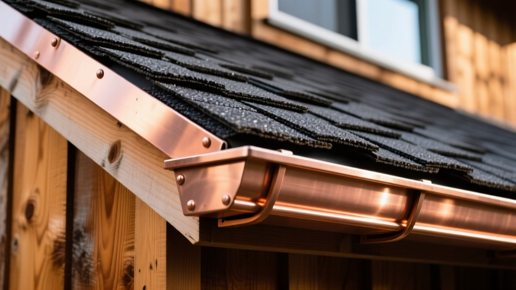
Material Performance Matrix by Base Element
Before addressing specific climates, it is necessary to establish the baseline physical properties of standard flashing materials. The following matrix outlines the optimal use cases and inherent vulnerabilities of common flashing stock.
| Material | Standard Specification | Optimal Climate | Primary Vulnerability |
|---|---|---|---|
| Copper (Cold Rolled) | 16 oz or 20 oz (ASTM B370) | Coastal, High-Precipitation | Galvanic corrosion when paired with aluminum or untreated steel |
| Aluminum Trim Coil | 0.032" or 0.040" (H14/H24 temper) | Inland, Temperate, Arid | Severe pitting and oxidation in salt-air or high-alkalinity (masonry) environments |
| Galvanized Steel | 26-gauge or 24-gauge (G90 coating) | Cold, High-Wind (when painted) | Red rust at sheared edges; zinc depletion in acid-rain zones |
| Stainless Steel | 24-gauge (Type 304 or 316) | Coastal, Industrial | High material cost; work-hardening during field forming |
| PVC / TPO Membranes | 45-mil to 60-mil reinforced | Commercial Flat Roofs, Temperate | Plasticizer migration and UV embrittlement in extreme heat |
Coastal and High-Salt Environments: The Corrosion Battleground
In coastal zones defined by continuous salt spray and high humidity, standard aluminum and galvanized steel flashings are liabilities. Salt accelerates the electrochemical breakdown of zinc coatings and causes rapid pitting in aluminum trim coil. Within 3 to 5 years, aluminum step flashing in a marine environment will develop pinhole leaks, rendering the roof envelope compromised.
Never install copper flashing in direct contact with aluminum gutters, galvanized steel roof panels, or untreated zinc alloys. The presence of saltwater acts as a highly conductive electrolyte, causing the less noble metal (aluminum or zinc) to corrode rapidly. Always use dielectric separation membranes or isolate metals using heavy-duty rubberized underlayment.
Required Specifications for Marine Zones
- Copper: Use 16-ounce or 20-ounce cold-rolled copper. According to the Copper Development Association, copper develops a protective patina that actively resists salt-spray degradation, making it the most durable long-term investment for coastal step and valley flashing.
- Stainless Steel: If copper is aesthetically prohibited, specify Type 316 stainless steel (marine grade) rather than Type 304. Type 316 contains molybdenum, which specifically inhibits chloride-induced pitting.
- Fasteners: All nails or screws securing the flashing must match or exceed the nobility of the flashing metal. Use silicon bronze ring-shank nails for copper, and 316 stainless steel screws for steel flashings.
Cold Climates and Ice Dam Zones: Managing Thermal Shock
In regions experiencing prolonged sub-freezing temperatures and heavy snow loads, the primary threats to flashing are ice dam water backup and extreme thermal expansion and contraction. When snow melts on a warm upper roof and refreezes at the colder eaves, water can back up under the shingles and pool against the step flashing and sidewall counter-flashing.
Oversizing for Ice Dam Protection
Standard asphalt shingle step flashing typically measures 5 inches by 7 inches. In heavy snow-load zones (e.g., ASCE 7 ground snow loads exceeding 50 psf), this is insufficient. Water backup from ice dams can easily exceed the 2-inch headlap provided by standard dimensions.
- Upgrade Dimensions: Specify 8-inch by 10-inch step flashing for all wall-to-roof intersections in cold climates. This provides a minimum 5-inch vertical water barrier above the ice and water shield line.
- Ice Barrier Integration: Per guidelines referenced by the National Roofing Contractors Association (NRCA), self-adhering polymer-modified bitumen underlayment (ice and water shield) must extend a minimum of 24 inches past the interior warm wall line. The step flashing must be layered over this membrane, not directly on the roof deck.
Continuous metal flashings (like long runs of apron flashing or parapet coping) will expand and contract significantly between summer highs and winter lows. For any continuous metal run exceeding 20 feet, you must incorporate a soldered expansion joint or a mechanical slip joint with a butyl rubber seal to prevent the metal from buckling and tearing the fastener holes.
High-Heat and UV-Intensive Desert Regions
Desert climates subject roofing materials flashing to extreme diurnal temperature swings and relentless ultraviolet (UV) radiation. Roof surface temperatures can easily exceed 160°F (71°C) in the summer, while dropping below freezing in the winter.
The Failure of Synthetics and Uncoated Metals
Standard EPDM rubber flashings and unreinforced PVC membranes suffer from plasticizer migration and UV embrittlement in these conditions, often cracking within a decade. Furthermore, bare galvanized steel reflects intense sunlight but absorbs massive heat, causing severe thermal bowing if not properly hemmed and cleated.
Desert-Optimized Flashing Strategy
- Kynar 500 (PVDF) Coated Steel: Specify 24-gauge galvanized steel coated with a 70% PVDF resin (commonly known as Kynar 500). PVDF coatings retain color and flexibility under extreme UV exposure and can withstand surface temperatures up to 250°F without degrading.
- Reflective TPO for Flat Roofs: For commercial low-slope applications, use 60-mil or 80-mil reinforced TPO (Thermoplastic Polyolefin) flashing membranes. TPO is inherently UV-stable and does not contain the plasticizers that cause PVC to become brittle over time.
- Sealant Chemistry: Avoid standard polyurethane caulks, which crack and chalk under intense UV. Specify polyether-based sealants (such as ChemCurb or Geocel ProFlex). Polyethers are UV-stable, do not shrink during curing, and maintain a Shore A hardness that allows for joint movement without tearing.
High-Wind and Hurricane-Prone Corridors
In Wind-Borne Debris Regions (WBDR) and High-Velocity Hurricane Zones (HVHZ), flashing failure rarely occurs due to material degradation; it occurs due to mechanical uplift and fastener withdrawal. When wind creates negative pressure over a roof, it pulls upward on the shingles and the underlying step flashing. If the flashing is inadequately secured, it pulls out of the wall joint, allowing wind-driven rain to enter the structure.
Uplift Resistance and Fastening Protocols
Adhering to the Insurance Institute for Business & Home Safety (IBHS) FORTIFIED Home standards is critical for wind resilience. FORTIFIED standards dictate strict fastening schedules for all roof perimeter and penetration flashings.
- Ring-Shank Nails Only: Smooth-shank roofing nails have virtually no withdrawal resistance under cyclic wind loads. All step flashing and drip edge must be secured using hot-dipped galvanized ring-shank nails (minimum 11-gauge, 1-inch penetration into the roof deck).
- Fastener Spacing: Reduce standard fastener spacing from 8 inches on center to a maximum of 4 inches on center for all perimeter drip edges, rake edges, and continuous headwall flashings.
- Mechanical Locking: For parapet and gravel stop flashings, do not rely solely on face-fastening. Use a continuous cleat system where the fascia face of the flashing mechanically locks into a receiver cleat that is bolted to the structural framing. This transfers wind uplift loads directly to the building skeleton rather than the roof deck edge.
Critical Installation Tolerances and Clearances
Regardless of the climate zone or material selected, the physical geometry of the flashing installation dictates its long-term performance. Improper clearances lead to capillary action, mortar corrosion, and concealed water intrusion.
The 1/4-Inch Masonry Rule
When installing counter-flashing or reglets into masonry, stucco, or brick mortar joints, the bottom edge of the metal must never rest directly on the roof surface or the horizontal masonry ledge. Mortar is highly alkaline and will aggressively corrode aluminum and galvanized steel. Furthermore, direct contact allows capillary action to draw water upward behind the flashing.
- Maintain a strict 1/4-inch to 3/8-inch clearance between the bottom hem of the counter-flashing and the base flashing or roof surface.
- Seal the reglet (the cut in the masonry) with a high-modulus, non-sag polyether sealant, tooling it to a slight downward slope to shed water away from the joint.
Headlap and Weave Requirements
For step flashing integrated with asphalt or composite shingles, the metal must be woven into the shingle courses, not laid continuously over them. Each piece of step flashing must overlap the piece below it by a minimum of 2 inches. In high-wind zones, increase this headlap to 3 inches to prevent wind-driven rain from bypassing the interlocking layers during severe storms.
- Coastal: 16 oz Copper or 316 Stainless; silicon bronze fasteners.
- Cold/Snow: 8x10 inch oversized step flashing; integrated with 24" ice barrier.
- Desert/Heat: 24-gauge PVDF coated steel; polyether sealants.
- High-Wind: Ring-shank nails at 4" O.C.; mechanical cleat systems for edges.
Specifying the correct roofing materials flashing requires looking beyond the initial material cost and evaluating the total lifecycle performance against local environmental stressors. By matching the metallurgical properties and installation geometry to the specific climate zone, contractors and architects can eliminate the vast majority of premature envelope failures and warranty callbacks.
Written by
Marcus ChenMarcus Chen is a licensed structural engineer (PE) and building materials analyst with over 12 years of experience across residential, commercial, and industrial construction. He holds a Master of Science in Civil Engineering from UC Berkeley and spent six years at Thornton Tomasetti before transitioning to independent consulting and technical writing. Marcus specializes in material selection for seismic-prone regions, concrete reinforcement strategies, and lifecycle cost analysis. His work has been cited by the American Concrete Institute (ACI) and the Structural Engineers Association of California (SEAOC). When he is not on a job site or at his desk, you will find him hiking the Sierra Nevada or restoring a 1920s craftsman bungalow in Oakland, CA.
More from Marcus Chen
View all
Construction Cost
How Much Did the Eiffel Tower Cost to Build?
How much did the Eiffel Tower cost to build in 1889? We adjust for inflation and compare its budget to modern skyscraper construction.
Aug 4, 2026
Fire Resistance
What Is a Fire Resistant Material? Testing & Certification Guide
Discover what is a fire resistant material through ASTM and UL testing. Learn how fire ratings, certifications, and assemblies work in construction.
Aug 4, 2026
Construction Cost
How Much Did the Burj Khalifa Cost to Build?
How much did the Burj Khalifa cost to build? We break down the $1.5B project and extract 5 money-saving strategies for your next build.
Jul 30, 2026