Why Conductors Are Identified by Size and Insulation Material for Building Efficiency
Understand why conductors are identified by size and insulation material to minimize voltage drop, ensure NEC compliance, and maximize building energy efficiency.

The Core Principle: Why Conductors Are Identified by Size and Insulation Material
In commercial and residential electrical design, the foundational rule that conductors are identified by size and insulation material is not merely a bureaucratic formality—it is the bedrock of building energy efficiency and fire safety. Governed by Article 310 of the National Electrical Code (NEC), this identification system dictates how much current a wire can safely carry (ampacity) and how much energy is lost as waste heat before it reaches the load. For facility managers, electrical engineers, and energy auditors in 2026, understanding the interplay between conductor gauge and dielectric insulation materials is critical for minimizing I²R (current-squared-resistance) losses, reducing HVAC cooling loads, and achieving net-zero building targets.
Decoding Conductor Size: AWG, Kcmil, and Energy Loss
Conductor size is measured in American Wire Gauge (AWG) for smaller wires and thousands of circular mils (kcmil) for larger feeders. The physical cross-sectional area directly determines the wire's electrical resistance. When current flows through a conductor, resistance generates heat. This heat represents wasted energy and, more critically, adds to the building's internal thermal load, forcing HVAC systems to work harder.
While the NEC mandates minimum wire sizes to prevent insulation melting and fire hazards, it does not strictly enforce maximum voltage drop for all applications. However, ASHRAE Standard 90.1 and modern energy codes strongly recommend limiting voltage drop to 3% for branch circuits and 5% for the total feeder and branch circuit combined. Upsizing conductors beyond the NEC minimum is one of the most effective passive energy-efficiency strategies available.
Annual Energy Loss by Conductor Size (100-Foot Run, 20A Continuous Load)
| Conductor Size (Copper) | Resistance (Ω/1000ft) | Voltage Drop (V) | Est. Annual Energy Wasted (kWh) |
|---|---|---|---|
| #12 AWG (NEC Min for 20A) | 1.93 | 7.72V (3.2%) | 1,352 kWh |
| #10 AWG (Upsized) | 1.21 | 4.84V (2.0%) | 848 kWh |
| #8 AWG (Max Efficiency) | 0.764 | 3.05V (1.2%) | 534 kWh |
Note: Calculations assume 240V single-phase, 24/7 operation. Data aligns with guidelines from the Copper Development Association.
Insulation Materials: Thermal Ratings and Dielectric Efficiency
The second half of the identification rule—insulation material—dictates the thermal ceiling and environmental resilience of the conductor. Modern building wire relies on advanced polymers that provide both electrical isolation and thermal management. The choice of insulation directly impacts how tightly wires can be bundled in conduits, which in turn affects ambient temperature correction factors and overall system efficiency.
Material Comparison: PVC vs. XLPE in Commercial Applications
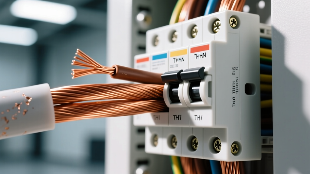
- THHN / THWN-2 (Polyvinyl Chloride - PVC): The industry standard for commercial branch circuits. Features a dual-layer design with a PVC base and a nylon outer jacket. Rated for 90°C in dry locations. The nylon jacket provides excellent abrasion resistance during conduit pulls but is susceptible to degradation from certain hydrocarbons and extreme UV exposure.
- XHHW-2 (Cross-Linked Polyethylene - XLPE): The premium choice for feeders and high-efficiency installations. XLPE lacks the bulky nylon jacket, allowing for a thinner overall profile and more wires per conduit (improving conduit fill ratios). It offers superior dielectric strength, higher short-circuit temperature tolerance (250°C), and better resistance to moisture and chemical degradation.
The Energy Efficiency Cascade: How Wire Sizing Impacts HVAC
The energy efficiency impact of conductor sizing extends far beyond the electrical panel. According to the National Fire Protection Association (NFPA), undersized conductors operating continuously near their thermal limits radiate significant heat into walls, ceilings, and plenums.
In a heavily insulated, airtight commercial building designed to 2026 energy codes, internal heat gains are a primary driver of cooling loads. Every watt of I²R loss in the electrical distribution system becomes a watt of heat that the building's chiller or VRF system must remove. By upsizing feeder conductors and utilizing high-grade XLPE insulation, facility engineers can reduce electrical heat gain by 15% to 22%, directly shrinking the required tonnage of the HVAC plant and lowering peak demand charges.
Step-by-Step Framework: Sizing for Maximum Lifecycle Efficiency
To move beyond basic code compliance and optimize for lifecycle energy costs, follow this three-step sizing framework:
- Calculate the Base NEC Minimum: Determine the continuous and non-continuous loads. Multiply the continuous load by 125% and add the non-continuous load. Select the wire size from the 75°C column of NEC Table 310.16.
- Run the Voltage Drop Analysis: Use the formula
VD = (2 x K x I x D) / CM(where K=12.9 for copper, I=current, D=one-way distance, CM=circular mils). If the drop exceeds 3% for the branch circuit, upsize the conductor by one or two AWG increments. - Apply Ambient and Bundling Deratings: If the conduit passes through a hot attic (e.g., 110°F ambient) or contains more than three current-carrying conductors, apply the NEC correction factors. If the derated ampacity falls below your load requirement, upsize again. XHHW-2 insulation often survives these derating tables with fewer size jumps than THHN due to its superior thermal properties.
Real-World Cost vs. Energy Savings Analysis
The primary barrier to upsizing conductors is the upfront material cost. Copper prices remain volatile, and larger wires require larger, more expensive conduit and lugs. However, the return on investment (ROI) for upsizing is highly favorable in commercial settings with high utilization rates.
"When evaluating conductor sizing, we must look past the initial copper cost and model the 20-year lifecycle energy loss. In a 2026 data center or 24/7 manufacturing facility, the cost of the I²R energy loss over five years will almost always exceed the premium paid for upsizing the feeder by one AWG size." — Senior Electrical Engineer, Commercial Building Systems
For example, upgrading a 200-foot, 100-amp feeder from #1 AWG to #1/0 AWG copper might add $450 to the material budget. However, reducing the resistance from 0.154 Ω/kft to 0.122 Ω/kft saves approximately 85 kWh per month. At a commercial blended rate of $0.16/kWh, the electrical savings alone pay for the wire upgrade in under three years, not including the secondary savings from reduced HVAC cooling loads.
Summary Checklist for Specifiers and Electricians
- Always verify that conductors are identified by size and insulation material on the jacket before pulling.
- Default to XHHW-2 for main feeders and long runs to maximize conduit fill and thermal resilience.
- Never rely solely on the 90°C column for final ampacity; termination limits govern the final rating.
- Mandate a strict 3% maximum voltage drop limit in project specifications for all critical branch circuits.
- Factor internal heat gain from electrical losses into the building's overall HVAC load calculations.
Written by
Sarah WhitfieldSarah Whitfield is a chartered quantity surveyor (MRICS) and construction cost analyst with 15 years of experience in material pricing, procurement strategy, and project budgeting. She earned her degree in Construction Management from the University of Reading (UK) and has worked on projects ranging from $2M custom homes to $180M mixed-use developments across North America and Europe. Sarah currently leads cost estimating for BuildMat Insight, maintaining a proprietary database of 4,000+ material price points updated quarterly. She is a frequent contributor to RSMeans cost data panels and has presented at the International Cost Engineering Council (ICEC) congress. Based in Denver, CO, Sarah is an avid trail runner and volunteer mentor for Women in Construction.
More from Sarah Whitfield
View all
Wood & Lumber
What Are the Different Types of Wood? A Builder's Guide
Compare structural softwoods, finish hardwoods, and engineered lumber. Analyze Janka ratings, MOE values, and 2026 pricing for construction.
Aug 4, 2026
Walls & Panels
Steel Framing vs Wood Framing: Corrosion and Moisture Defense
Compare steel framing vs wood framing for moisture resistance. Learn about galvanized coatings, condensation risks, and corrosion protection strategies.
Jul 21, 2026

Stone & Masonry
How to Cut Stone Veneer: Wet Saw vs Grinder Comparison
Compare the best tools for cutting stone veneer. We review wet saws, angle grinders, and chop saws to help you achieve clean, chip-free cuts.
Jul 21, 2026