Gypsum Board Control Joint Detail: Specs, Spacing, and Installation
Master the gypsum board control joint detail to prevent drywall cracking. Learn ASTM spacing rules, product types, and step-by-step installation methods.

The Physics of Drywall Movement: Why Control Joints Matter
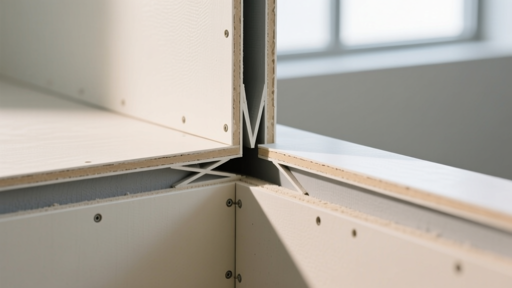
Gypsum board is a rigid, brittle composite. While it possesses high compressive strength, it has virtually no tensile elasticity. When a building experiences lateral drift, thermal expansion, hygroscopic swelling, or live-load deflection, the structural frame moves. If the drywall assembly is installed as a single monolithic plane, it will absorb this kinetic energy and fail along its weakest axis—resulting in diagonal shear cracking or fastener pop-outs. The gypsum board control joint detail is an engineered relief mechanism designed to localize and absorb this movement, sacrificing a hidden, flexible vinyl or paper extrusion to preserve the visual integrity of the finished wall or ceiling.
ASTM C840 and GA-216 Spacing Requirements
The placement of control joints is not arbitrary; it is strictly governed by ASTM C840 (Standard Specification for Application and Finishing of Gypsum Board) and the Gypsum Association's GA-216 guidelines. These standards dictate maximum uninterrupted surface areas to prevent stress accumulation.
| Surface Type | Maximum Linear Spacing | Maximum Area Between Joints | Aspect Ratio Limit |
|---|---|---|---|
| Ceilings | 30 feet (9.1 m) | 2,500 sq. ft. (232 m²) | Ratio of length to width must not exceed 3:1 |
| Walls | 30 feet (9.1 m) | 3,000 sq. ft. (278 m²) | Ratio of length to width must not exceed 3:1 |
| Corridors / Long Runs | Every 30 linear feet | N/A | Must align with structural expansion joints |
Product Selection: Vinyl vs. Paper-Faced vs. Flexible Extrusions
Selecting the correct extrusion profile depends on the anticipated movement, the finishing level (Level 4 vs. Level 5), and the lighting conditions. Below is a breakdown of the primary product categories available in 2026.
1. Standard Vinyl V-Groove Control Joints
Products like the ClarkDietrich 1/2-inch Vinyl Control Joint or National Gypsum Gold Bond Vinyl Control Joint feature a rigid PVC flange with a flexible co-extruded V-groove center.
Best for: Standard commercial partitions, Level 4 finishes, and areas with standard ambient lighting.
Movement Tolerance: Typically accommodates up to 1/4-inch of lateral movement.
2. High-Deflection Flexible Joints
The USG Sheetrock Brand Duraflex Control Joint utilizes a proprietary flexible polymer that allows for significant compression and extension without tearing.
Best for: High-rise construction, seismic zones, and buildings with high live-load deflection rates.
Movement Tolerance: Accommodates up to 1/2-inch (12.7 mm) of movement.
3. Paper-Faced Control Joints
Products like the Trim-Tex Paper-Faced Expansion Joint feature a vinyl core wrapped in drywall paper.
Best for: Level 5 finishes and areas with critical raking light (e.g., skylights, wall-wash LEDs). The paper flanges blend seamlessly into the gypsum board, eliminating the 'telegraphing' effect where rigid vinyl flanges cast shadows under harsh lighting.
Step-by-Step Execution of the Gypsum Board Control Joint Detail
Proper installation requires strict adherence to sequencing. The most common cause of joint failure is improper finishing, not improper framing.
- Align with Structural Joints: Before hanging any board, verify the architectural drawings. The drywall control joint must align perfectly with the building's structural expansion joints and the framing's deflection tracks. Never offset them.
- Cut and Fit the Board: Cut the gypsum board so that the edges fall cleanly into the flanges of the control joint. Do not force the board; leave a 1/8-inch gap between the board edge and the back of the joint's flange to allow for compression.
- Fasten the Extrusion: For vinyl joints, staple or screw the flanges to the framing. If using a paper-faced joint, apply a continuous bead of joint compound to the flanges, embed the joint, and smooth it out.
- Stagger End Joints: Control joints are typically sold in 10-foot lengths. When stacking them vertically on a wall, stagger the end cuts by at least 12 inches to prevent a continuous horizontal weak point.
- Finish the Flanges (Not the Groove): Apply joint compound only to the flanges. Feather the edges to blend with the wall.
Never, under any circumstances, apply joint compound into the V-groove of a vinyl control joint. The groove must remain completely clean and flexible. If compound gets into the groove, scrape it out immediately while wet. Once cured, compound in the groove will act as a rigid bridge, defeating the purpose of the joint and guaranteeing a crack.
Common Failure Modes and Troubleshooting Matrix
When a control joint fails, it is almost always due to an installation error rather than a product defect. Use this diagnostic matrix to identify and correct field issues.
| Symptom | Root Cause | Corrective Action |
|---|---|---|
| Hairline crack running directly down the center of the V-groove. | Joint compound was inadvertently applied over the flexible groove, creating a rigid bridge. | Rake out the crack with a utility knife. Clean the groove. Do not re-mud. Paint with a flexible elastomeric coating if necessary. |
| Diagonal tearing at the corners of door frames adjacent to the joint. | Control joint was not installed, or was placed too far from the stress concentration point of the door header. | Install a control joint directly above the door header or use a specialized door-frame expansion profile. |
| Visible ridge or 'telegraphing' of the flange under raking light. | Rigid vinyl flanges were used in a Level 5 / critical lighting environment without sufficient skim coating. | Switch to paper-faced control joints for future phases, or apply a full Level 5 skim coat over the entire wall to equalize porosity and texture. |
| Flange bulging or fastener pop-outs within 12 inches of the joint. | Drywall panels were forced tightly against the back of the flange during installation, causing compression buckling. | Remove the panel, trim 1/8-inch off the edge, and reinstall to allow proper expansion clearance. |
Expert References and Code Compliance
For commercial projects, the authority having jurisdiction (AHJ) will require documentation that the gypsum board control joint detail complies with local building codes and industry standards. Always reference the following documents in your submittals:
- ASTM C840: Standard Specification for Application and Finishing of Gypsum Board. This is the foundational code document dictating maximum spacing and material requirements.
- GA-216 (Application and Finishing of Gypsum Panel Products): Published by the Gypsum Association, this manual provides the definitive visual details and framing requirements for control joints, including head-of-wall deflection clearances.
- UL Design Numbers: If the partition is fire-rated (e.g., 1-hour or 2-hour), the control joint must be part of a tested UL assembly. Using a non-rated vinyl joint in a rated wall voids the fire rating. Always verify the UL design number (e.g., UL U419) and ensure the specific control joint profile is listed within that assembly's material specifications.
By treating the gypsum board control joint detail as a dynamic structural component rather than a mere finishing accessory, contractors can eliminate callbacks, prevent unsightly cracking, and deliver commercial interiors that withstand the long-term physical realities of building movement.
Written by
Sarah WhitfieldSarah Whitfield is a chartered quantity surveyor (MRICS) and construction cost analyst with 15 years of experience in material pricing, procurement strategy, and project budgeting. She earned her degree in Construction Management from the University of Reading (UK) and has worked on projects ranging from $2M custom homes to $180M mixed-use developments across North America and Europe. Sarah currently leads cost estimating for BuildMat Insight, maintaining a proprietary database of 4,000+ material price points updated quarterly. She is a frequent contributor to RSMeans cost data panels and has presented at the International Cost Engineering Council (ICEC) congress. Based in Denver, CO, Sarah is an avid trail runner and volunteer mentor for Women in Construction.
More from Sarah Whitfield
View all
Wood & Lumber
What Are the Different Types of Wood? A Builder's Guide
Compare structural softwoods, finish hardwoods, and engineered lumber. Analyze Janka ratings, MOE values, and 2026 pricing for construction.
Aug 4, 2026

Walls & Panels
Steel Framing vs Wood Framing: Corrosion and Moisture Defense
Compare steel framing vs wood framing for moisture resistance. Learn about galvanized coatings, condensation risks, and corrosion protection strategies.
Jul 21, 2026

Stone & Masonry
How to Cut Stone Veneer: Wet Saw vs Grinder Comparison
Compare the best tools for cutting stone veneer. We review wet saws, angle grinders, and chop saws to help you achieve clean, chip-free cuts.
Jul 21, 2026