Suspended Gypsum Board Ceiling System: Exact Specs & Dimensions
Master suspended gypsum board ceiling system specs. Get exact dimensions, framing spacing, hanger wire gauges, and sag prevention guidelines.

Core Component Specifications: Grid, Hangers, and Channels
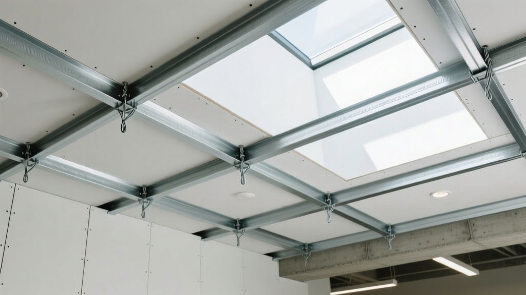
Designing a suspended gypsum board ceiling system requires strict adherence to dimensional tolerances and load-bearing specifications. Unlike direct-applied ceilings, suspended systems rely on a complex matrix of hangers, main runners, and furring channels. The structural integrity of the assembly is governed by ASTM C635, which dictates the manufacturing and performance standards for suspended ceiling grids.
Hanger Wire and Fastener Dimensions
The vertical support mechanism must resist both dead loads and dynamic uplift. For standard commercial and residential applications, hanger wires must meet precise dimensional criteria:
- Minimum Wire Gauge: 12-gauge (0.081-inch diameter) galvanized steel wire is the absolute minimum for standard suspended gypsum ceilings. For heavy-duty or seismic applications, 10-gauge (0.105-inch) or 8-gauge (0.135-inch) wire is required.
- Attachment Spacing: Hangers must be spaced no more than 4 feet apart along the main runners, and the first hanger must be located within 2 feet of the perimeter wall.
- Angle of Suspension: Hanger wires must not deviate more than 15 degrees from plumb. Angled wires introduce lateral forces that can cause the grid to rack or buckle under load.
Furring Channel and Grid Specs
| Component | Standard Dimensions | Material / Gauge | Maximum Spacing |
|---|---|---|---|
| Main Runners (T-Bars) | 1-1/2" deep x 15/16" wide | Galvanized Steel, 15-gauge | 48" on center (O.C.) |
| Cold-Rolled Furring Channels | 1-1/2" deep x 3/4" wide | Galvanized Steel, 25-gauge min. | 16" or 24" O.C. (per board spec) |
| Hat Channels (Furring) | 7/8" deep x 2-1/2" wide | Galvanized Steel, 25-gauge | 24" O.C. (requires 5/8" board) |
| Perimeter Angle | 1" x 1" or 1-1/4" x 1-1/4" | Galvanized Steel, 22-gauge | Continuous at all walls |
Gypsum Board Panel Dimensions & Selection
Selecting the correct gypsum board thickness and type is the most critical decision in preventing ceiling sag—a common failure mode in suspended assemblies. The Gypsum Association Construction Guide outlines strict correlations between board thickness, framing spacing, and environmental humidity.
Standard 1/2-inch gypsum board installed perpendicular to framing spaced 24 inches O.C. has a high probability of sagging, especially in unconditioned spaces or newly constructed buildings where ambient humidity exceeds 70% before HVAC stabilization. Always use specialized sag-resistant 1/2-inch panels or upgrade to 5/8-inch panels for 24-inch O.C. spacing.
1/2-Inch vs. 5/8-Inch Ceiling Panels
Modern manufacturing has introduced ultralight panels that alter traditional weight-to-strength ratios. When specifying materials, consider the following dimensional and physical properties:
- 1/2-Inch Ultralight Ceiling Board (e.g., USG Sheetrock UltraLight): Weighs approximately 1.25 lbs per square foot. Engineered with reinforced glass fibers to allow 24-inch O.C. framing spacing without sagging, provided the space is conditioned.
- 5/8-Inch Standard / Firecode Board: Weighs approximately 2.2 lbs per square foot. Offers superior rigidity and is mandatory for Type X fire-rated suspended assemblies requiring 1-hour or 2-hour fire resistance ratings under UL Design specifications.
Framing Spacing & Deflection Limits
The dimensional spacing of the furring channels directly dictates the allowable live load deflection of the structural deck above. If the primary structure deflects beyond acceptable limits, the suspended gypsum ceiling will crack at the joints.
Live Load Deflection Criteria
Building codes and industry standards establish maximum deflection ratios for the structure supporting the ceiling grid:
- L/240 Limit: Acceptable for plaster ceilings. The structure can deflect up to 1/240th of the span length.
- L/360 Limit: The strict requirement for gypsum board ceilings. For a 30-foot span beam, the maximum allowable deflection under live load is 1 inch. Exceeding this dimension guarantees fastener popping and joint compound fracturing.
Fastener Spacing Dimensions
Proper fastener density ensures the board acts as a unified diaphragm. For suspended ceilings, screws must be Type S or Type G bugle-head screws, sized to penetrate the steel framing by a minimum of 3/8-inch.
- Field Spacing: Maximum 12 inches O.C. for 16-inch framing; maximum 12 inches O.C. for 24-inch framing.
- Perimeter Spacing: Maximum 8 inches O.C. along all edges and ends.
- Edge Distance: Screws must be placed no less than 3/8-inch and no more than 5/8-inch from the board edge to prevent paper tear-out.
Seismic & Acoustic Dimensional Requirements
In regions governed by strict seismic codes or projects requiring high Sound Transmission Class (STC) ratings, the dimensional parameters of the suspended ceiling must be modified to accommodate movement and vibration isolation.
Seismic Perimeter Clearances
Under the latest International Building Code (IBC) updates for Seismic Design Categories D, E, and F, suspended ceilings must be decoupled from the surrounding structure to prevent crushing during lateral displacement.
Maintain a minimum 2-inch clearance between the ceiling grid and all vertical obstructions (walls, columns, ductwork). Do not fill this gap with rigid joint compound. Use flexible acoustic sealant or a slip-track perimeter molding that allows the ceiling plane to move independently of the wall framing.
Acoustic Isolation Dimensions
To achieve STC ratings of 50 or higher, the suspended system must utilize resilient channels or isolation clips. When using 1/2-inch or 5/8-inch resilient channels (RC-1):
- Channel Orientation: Must be installed perpendicular to the main framing runners.
- Vertical Drop: Resilient channels typically drop the ceiling plane by exactly 1/2-inch to 5/8-inch. This dimension must be accounted for when calculating HVAC diffuser drops and recessed lighting housing depths.
- Isolation Clip Deflection: Neoprene isolation clips (e.g., Kinetics IsoMax) provide a 3/8-inch drop and require a minimum 1-inch air gap above the gypsum board to function effectively without bottoming out under load.
Common Installation Failures & Dimensional Fixes
Even with perfect material specifications, dimensional errors during installation compromise the system. Below is a troubleshooting matrix for common field issues:
| Failure Mode | Dimensional Cause | Corrective Specification |
|---|---|---|
| Grid Rack / Twist | Hanger wires installed >15 degrees off plumb. | Re-plumb all hangers; add diagonal lateral bracing wires every 20 feet in both directions. |
| Visible Board Sag | 1/2" standard board on 24" O.C. framing in high humidity. | Remove and replace with 5/8" board or 1/2" sag-resistant Ultralight board; ensure HVAC is running. |
| Perimeter Cracking | Board installed tight against wall with no expansion gap. | Cut board to leave a 1/4-inch gap at all walls; cover with L-bead or shadowline molding. |
| Fastener Popping | Primary structure deflection exceeds L/360 limit. | Install an independent ceiling grid suspended directly from the roof deck, bypassing the deflecting joists. |
Precision in a suspended gypsum board ceiling system is non-negotiable. By strictly enforcing hanger gauge limits, respecting live-load deflection ratios, and selecting the correct panel thickness for the specified framing spacing, contractors can deliver assemblies that remain flat, crack-free, and structurally sound for the lifespan of the building.
Written by
Elena RodriguezElena Rodriguez is a civil engineer and technical writer specializing in concrete technology, masonry systems, and ASTM/ACI compliance. She earned her B.S. in Civil Engineering from Texas A&M University and spent a decade at a materials testing laboratory, performing over 2,000 concrete compressive strength tests and masonry prism evaluations. Elena is an ACI-certified Field Testing Technician (Grade I) and a member of ASTM Committee C12 on Natural Building Stone. She currently consults on forensic engineering cases involving concrete failures and moisture intrusion. Based in San Antonio, TX, Elena is a proud member of the Society of Women Engineers (SWE) and coaches her daughter's FIRST Robotics team.
More from Elena Rodriguez
View all
Walls & Panels
Cost Analysis: Light Gauge Steel Framing Advantages and Disadvantages
Evaluate light gauge steel framing advantages and disadvantages through a strict cost analysis lens, comparing material, labor, and lifecycle expenses.
Aug 4, 2026
Walls & Panels
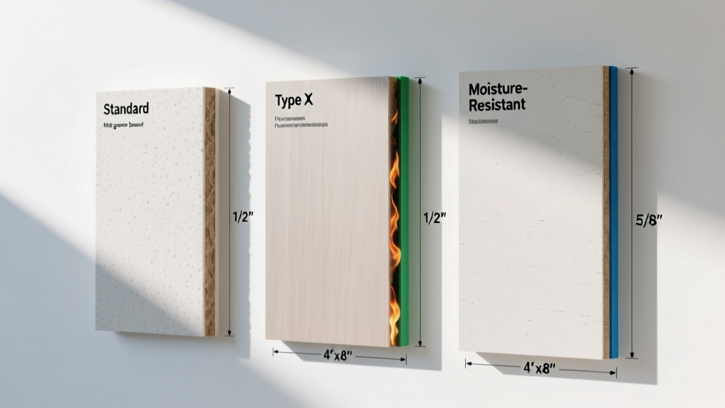
Gypsum Board Types: Exact Specifications, Thickness & Dimensions
Compare standard, Type X, and moisture-resistant gypsum board types. Get exact specifications, thicknesses, dimensions, and ASTM standards for your project.
Aug 4, 2026
Fire Resistance
Best Fire-Resistant Outdoor Decking Materials: 2026 Buyer Guide
Discover the best fire-resistant outdoor decking materials for 2026. Compare Class A PVC, aluminum, and hardwood options for WUI compliance and safety.
Aug 4, 2026