Exterior Steel Framing Specs: Gauge, Yield, and Coatings
Master exterior steel framing technical specs. Compare 33 vs 50 ksi yield strengths, G60/G90 coatings, and ASTM C955 deflection limits for modern builds.

Core Material Standards and Yield Strengths
Exterior steel framing for commercial and mid-rise residential envelopes operates under strict ASTM and AISI (American Iron and Steel Institute) guidelines. Unlike interior partition walls, exterior load-bearing and curtain-wall backup systems must resist complex wind shear, seismic drift, and dead loads from heavy cladding materials like masonry veneer or architectural precast panels.
- ASTM C955: Standard Specification for Load-Bearing (Transverse and Axial) Steel Studs, Runners (Tracks), and Bracing or Bridging, for Screw Application of Gypsum Panel Products and Metal Plaster Bases.
- ASTM C645: Standard Specification for Nonstructural Steel Framing Members (used strictly for non-load-bearing exterior soffits or furring).
- ASTM A1003: Standard Specification for Steel Sheet, Carbon, Metallic- and Nonmetallic-Coated for Cold-Formed Framing.
The structural capacity of exterior cold-formed steel (CFS) is dictated by its yield strength, measured in ksi (kips per square inch). Specifying the correct grade prevents catastrophic buckling under lateral wind loads.
Yield Strength Grade Matrix
| Grade | Yield Strength (Fy) | Tensile Strength (Fu) | Primary Exterior Application |
|---|---|---|---|
| Grade 33 | 33 ksi | 45 ksi | Non-load-bearing exterior furring, soffits, and light curtain-wall backup. |
| Grade 50 | 50 ksi | 65 ksi | Standard load-bearing exterior walls, shear walls, and multi-story curtain-wall studs. |
| Grade 80 | 80 ksi | 100 ksi | High-load transfer tracks, specialized headers, and heavy cantilevered parapets. |
Base Metal Thickness (BMT) vs. Design Thickness
A critical specification error in exterior framing occurs when architects and engineers confuse Base Metal Thickness (BMT) with Design Thickness. According to the American Iron and Steel Institute (AISI), the BMT is the thickness of the bare steel before any galvanization or paint coatings are applied. The Design Thickness includes the metallic coating and is the value used for structural engineering calculations.
In modern procurement, CFS is ordered by "mil" thickness (1 mil = 0.001 inches) rather than traditional gauge numbers, which can vary by manufacturer. The Steel Framing Industry Association (SFIA) mandates strict adherence to these mil designations to ensure structural integrity.
| Traditional Gauge | Design Thickness (Mils) | BMT (Mils) | 2026 Est. Cost (G90, 3-5/8" Web) |
|---|---|---|---|
| 20 Gauge | 33 mil | 30 mil | $3.45 - $4.10 / PLF |
| 18 Gauge | 43 mil | 40 mil | $4.20 - $4.95 / PLF |
| 16 Gauge | 54 mil (Standard) / 68 mil (Structural) | 50 mil / 64 mil | $5.80 - $6.75 / PLF |
| 14 Gauge | 97 mil | 93 mil | $8.50 - $9.90 / PLF |
Galvanization Coatings for Exterior Envelopes
Exterior steel framing is highly susceptible to condensation, bulk water intrusion, and galvanic corrosion when in contact with dissimilar metals or alkaline masonry. The zinc coating weight, measured in ounces per square foot (oz/sq ft) of total surface area (both sides combined), is the primary defense mechanism.
| Coating Designation | Total Zinc Weight | Exterior Suitability | Specific Use Case |
|---|---|---|---|
| G60 | 0.60 oz/sq ft | Poor / Not Recommended | Interior partitions only. Strictly prohibited for exterior envelopes by most commercial specs. |
| G90 | 0.90 oz/sq ft | Excellent (Standard) | Standard exterior wall framing, parapets, and soffits behind approved WRB systems. |
| AZ50 (Galvalume) | 0.50 oz/sq ft (55% Al, 43.4% Zn) | Superior (High Moisture) | Coastal zones (within 1,500 ft of saltwater), high-humidity agricultural facilities, and exposed soffits. |
Deflection Limits and Slip Track Engineering
Exterior framing must accommodate the live-load deflection of the primary structural frame (concrete slabs or structural steel beams) without transferring loads to the brittle exterior cladding. This is managed through deflection tracks (slip tracks) and strict L-ratio limits.
Cladding-Specific Deflection Limits
- L/240: The baseline requirement for flexible cladding systems, including EIFS (Exterior Insulation and Finish Systems), metal composite panels, and vinyl siding. A 20-foot wall can deflect up to 1 inch.
- L/360: Required for semi-rigid cladding like fiber cement boards and stucco over metal lath. A 20-foot wall is limited to 0.66 inches of deflection to prevent cracking.
- L/600: Mandatory for rigid masonry veneer (brick, stone, CMU) anchored to the steel backup. A 20-foot wall is limited to 0.4 inches of deflection to prevent masonry joint failure and tie-back snapping.
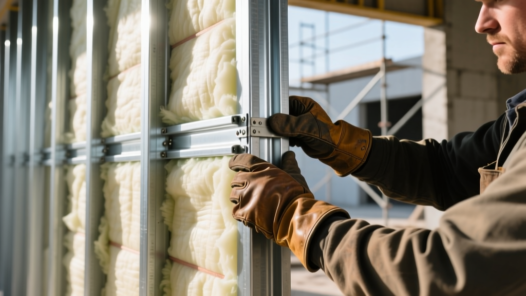
To achieve these limits without oversizing the stud web, engineers utilize bypass framing or deflection tracks. A standard deflection track features a deep leg (typically 1.5 to 2 inches larger than the stud depth) and a gap at the top of the stud. This gap must be filled with a compressible fire-stopping material, such as mineral wool, which maintains the fire rating while allowing vertical slab movement.
Fastener Matrices and Edge Distances
The structural continuity of exterior steel framing relies entirely on the shear and pull-over capacity of self-drilling screws. Using interior-grade drywall screws or incorrect hex-washer heads on exterior shear panels will result in immediate failure during high-wind events.
| Connection Type | Fastener Specification | Head Style | Minimum Edge Distance |
|---|---|---|---|
| Stud to Track (Standard) | #8 x 1/2" or #10 x 3/4" Self-Drilling | Pan-Head or Flat-Head | 1/2 inch from edge of sheet steel |
| Shear Wall Panel to Stud | #8 x 1" or #10 x 1-1/4" Self-Drilling | Pancake or Low-Profile Hex | 3/8 inch from panel edge |
| Heavy Clip Angle to Stud | #12 x 3/4" or #12 x 1" Self-Drilling | Hex-Washer Head (HWH) | 3/4 inch from edge of clip angle |
| Masonry Tie-Back to Stud | #12 x 1-1/4" Self-Drilling (Teks) | Hex-Washer Head (HWH) | 1 inch from stud flange edge |
Thermal Bridging Mitigation (ASHRAE 90.1 Compliance)
Steel is a highly conductive material (approximately 314 Btu·in/h·ft²·°F). An uninsulated 16-gauge steel stud will bypass cavity insulation, creating a massive thermal bridge that drops the effective R-value of the wall assembly by up to 50%. To comply with modern energy codes, including ASHRAE 90.1 standards, exterior steel framing must integrate continuous insulation (ci) and thermal break strategies.
Approved Thermal Break Strategies
- Exterior Continuous Insulation (ci): Installing rigid polyisocyanurate or mineral wool boards directly over the exterior sheathing. A minimum of R-10 ci is typically required in Climate Zones 4 and higher to prevent interstitial condensation on the cold steel flange.
- Thermal Spacer Blocks: Placing high-density polyurethane or neoprene pads between the steel stud flange and the exterior gypsum sheathing. This breaks the direct conductive path, improving the assembly U-factor by 12-18%.
- Slotted Web Studs: Utilizing specialized CFS studs with factory-punched longitudinal slots in the web. These slots increase the thermal path length through the steel, reducing thermal conductivity by up to 30% compared to solid-web studs. Note: Slotted studs have reduced shear capacity and must be engineered specifically for wind loads.
Critical Specification Errors and Failure Modes
Field failures in exterior steel framing rarely stem from the steel itself, but from improper detailing at the intersections of dissimilar materials.
Precise specification of gauge, yield strength, coating weight, and connection detailing ensures that exterior steel framing performs flawlessly under the rigorous demands of modern commercial building envelopes. Always cross-reference project-specific structural engineering drawings with the manufacturer's current load-span tables before finalizing procurement.
Written by
Sarah WhitfieldSarah Whitfield is a chartered quantity surveyor (MRICS) and construction cost analyst with 15 years of experience in material pricing, procurement strategy, and project budgeting. She earned her degree in Construction Management from the University of Reading (UK) and has worked on projects ranging from $2M custom homes to $180M mixed-use developments across North America and Europe. Sarah currently leads cost estimating for BuildMat Insight, maintaining a proprietary database of 4,000+ material price points updated quarterly. She is a frequent contributor to RSMeans cost data panels and has presented at the International Cost Engineering Council (ICEC) congress. Based in Denver, CO, Sarah is an avid trail runner and volunteer mentor for Women in Construction.
More from Sarah Whitfield
View all
Wood & Lumber
What Are the Different Types of Wood? A Builder's Guide
Compare structural softwoods, finish hardwoods, and engineered lumber. Analyze Janka ratings, MOE values, and 2026 pricing for construction.
Aug 4, 2026
Walls & Panels
Steel Framing vs Wood Framing: Corrosion and Moisture Defense
Compare steel framing vs wood framing for moisture resistance. Learn about galvanized coatings, condensation risks, and corrosion protection strategies.
Jul 21, 2026

Stone & Masonry
How to Cut Stone Veneer: Wet Saw vs Grinder Comparison
Compare the best tools for cutting stone veneer. We review wet saws, angle grinders, and chop saws to help you achieve clean, chip-free cuts.
Jul 21, 2026