Types of Foundations in Water Resources Engineering: Complete Guide
Explore the types of foundations in water resources engineering, covering gravity bases, caissons, uplift mitigation, and scour protection for dams.

The Unique Demands of Hydraulic Foundation Engineering
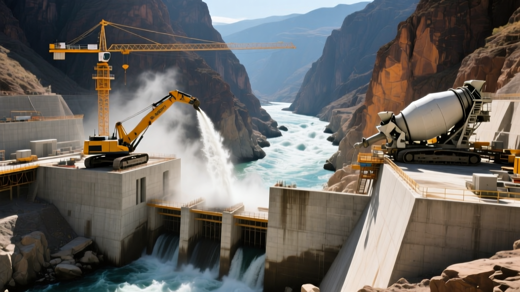
Standard commercial and residential foundation design primarily addresses vertical dead and live loads. In contrast, the types of foundations water resources engineering projects require must withstand complex, multi-directional forces. Structures such as dams, spillways, weirs, barrages, lock chambers, and large-scale pumping stations operate in aggressive hydraulic environments. These foundations must resist immense hydrostatic pressure, dynamic wave loading, seismic hydrodynamic forces, and the constant threat of sub-surface piping and scour.
Unlike terrestrial structures, hydraulic foundations are subject to uplift pressure governed by Archimedes' principle. Water percolating through soil or rock joints beneath a dam creates an upward hydrostatic force that can reduce the effective weight of the structure by up to 30%, severely compromising sliding and overturning stability.
Primary Types of Foundations in Water Resources Engineering
Selecting the correct foundation system depends on the structural typology, the geotechnical profile of the riverbed or reservoir floor, and the anticipated hydrological extremes. Below are the primary foundation systems utilized in modern hydraulic infrastructure.
1. Gravity Foundations (Mass and Roller-Compacted Concrete)
Gravity foundations rely on their massive weight to resist horizontal water thrust and uplift forces. They are the standard for concrete gravity dams and large weirs. Modern gravity foundations heavily utilize Roller-Compacted Concrete (RCC). RCC is a zero-slump concrete mix placed in horizontal lifts and compacted with vibratory rollers. To manage the heat of hydration in massive pours—which can cause thermal cracking and compromise structural integrity—RCC mixes often incorporate high-volume fly ash replacements (up to 60% of the cementitious material). The foundation base is typically keyed into sound bedrock, requiring extensive grouting to seal micro-fractures and reduce sub-surface permeability.
2. Drilled Shafts and Caisson Foundations
For deep-water structures, bridge piers over navigable channels, and lock walls where bedrock is buried under deep alluvial deposits, drilled shafts and pneumatic caissons are mandatory. Open-end steel pipe piles or large-diameter drilled shafts (often exceeding 2.5 meters in diameter) are driven or drilled through overburden soils to socket into bedrock. Because these are placed in submerged environments, concrete placement requires the tremie method. A tremie pipe deposits concrete from the bottom up, displacing the drilling slurry or water without segregating the mix. According to guidelines from the Federal Highway Administration Hydraulics Engineering division, deep foundations in scour-critical waterways must be designed assuming the total loss of soil support down to the maximum calculated scour depth.
3. Mat and Raft Foundations for Pumping Stations
Large municipal water intake facilities and wastewater pumping stations experience severe cyclic loading from heavy machinery and fluctuating internal water levels. A thickened mat or raft foundation distributes these concentrated dynamic loads over a wide area. To prevent differential settlement that could misalign massive pump impellers, the mat is often post-tensioned or heavily reinforced with epoxy-coated rebar to resist corrosion from the high-moisture environment. Drainage galleries and sump pits are cast directly into the mat to manage groundwater intrusion.
4. Anchored and Tie-Back Foundations
For slender hydraulic structures like sheet pile bulkheads, floodwalls, and certain cofferdams, the foundation itself lacks the mass to resist lateral water pressure. These systems utilize deep soil anchors or rock tie-backs. High-strength steel tendons are drilled deep into the stable earth or rock behind the structure, grouted under high pressure, and tensioned against the foundation wall. This creates an active resisting moment that prevents the foundation from kicking out at the toe.
Foundation Selection Matrix for Hydraulic Projects
The following matrix provides a decision framework for matching foundation types to specific water resources applications based on geotechnical and hydrological constraints.
| Foundation Type | Ideal Application | Subsurface Requirement | Scour Resistance | Uplift Mitigation Strategy |
|---|---|---|---|---|
| Gravity (RCC/Mass) | Dams, large spillways, barrages | Shallow, competent bedrock | High (mass resists displacement) | Drainage galleries, upstream grout curtains |
| Drilled Shafts / Caissons | Bridge piers, lock walls, deep-water intakes | Deep alluvial overburden to bedrock | Moderate (requires scour armoring) | Deep socketing into impermeable rock |
| Mat / Raft | Pump houses, treatment basins | Uniform compressible soils or rock | Low (requires backfill/protection) | Perimeter French drains, relief wells |
| Anchored Sheet Pile | Floodwalls, bulkheads, cofferdams | Cohesive soils or dense sands | Low (vulnerable to toe scour) | Deep embedment, tie-back anchors |
Critical Failure Modes: Piping, Uplift, and Scour
Understanding the types of foundations water resources engineering relies upon requires a deep knowledge of how these foundations fail. Hydraulic foundation failure rarely occurs due to simple bearing capacity exhaustion; it is almost always driven by water-soil interaction.
Piping and Internal Erosion
Piping occurs when seepage water beneath a foundation exerts enough exit gradient force to dislodge soil particles, creating a subterranean tunnel that eventually collapses the structure. Engineers use Bligh's Creep Theory and Lane's Weighted Creep Ratio to design the seepage path. To mitigate piping, foundations incorporate deep concrete cutoff walls, steel sheet pile lines, or upstream impervious clay blankets to lengthen the seepage path and reduce the hydraulic gradient. The US Bureau of Reclamation Dam Safety Program mandates rigorous piezometer monitoring to detect abnormal seepage rates that indicate internal erosion.
Scour Undermining
High-velocity water passing over spillways or through weir gates creates turbulent eddies that erode the riverbed downstream of the foundation. If the scour hole migrates beneath the foundation toe, the structure loses passive earth pressure and bearing support. Mitigation involves installing articulated concrete block (ACB) systems, such as ArmorFlex, or large riprap aprons designed using the Isbash equation to ensure stone sizes are heavy enough to resist the specific flow velocities.
Seismic Hydrodynamic Considerations
In seismically active regions, water resources foundations must account for hydrodynamic forces. During an earthquake, the water in a reservoir does not move in unison with the dam. According to Westergaard's added mass theory, the water exerts an additional impulsive pressure against the structure. The foundation must be rigid enough to transfer these dynamic loads into the bedrock without experiencing liquefaction in the underlying soils. The US Army Corps of Engineers Engineering Manuals provide specific dynamic analysis protocols for evaluating foundation-soil-structure interaction (SSI) under seismic loading, often requiring deep soil mixing or vibro-replacement stone columns to densify loose, saturated foundation soils prior to construction.
Modern Waterproofing and Joint Protection Systems
Because hydraulic foundations are poured in multiple lifts, construction joints are inevitable weak points. Modern water resources engineering employs advanced waterproofing technologies to ensure zero-leakage at these critical interfaces:
- PVC Dumbbell Waterstops: Extruded polyvinyl chloride profiles with bulbous ends that mechanically lock into the concrete, providing a tortuous path for migrating water.
- Hydrophilic Swelling Strips: Made from sodium bentonite or specialized acrylic polymers, these strips expand up to 400% of their original volume upon contact with moisture, sealing micro-cracks in the foundation joints.
- Crystalline Admixtures: Integral concrete admixtures (such as Xypex) that react with moisture and unhydrated cement particles to form insoluble needle-like crystals, permanently blocking capillary tracts within the foundation mass.
Frequently Asked Questions
How is uplift pressure physically reduced in a concrete dam foundation?
Uplift is reduced by installing a grout curtain near the upstream heel to block water ingress, combined with a network of drainage galleries and relief wells drilled deep into the foundation rock behind the curtain. This safely intercepts and channels seepage water away, dropping the hydrostatic pressure profile beneath the dam.
What is the difference between a cofferdam and a permanent hydraulic foundation?
A cofferdam is a temporary, watertight enclosure (often made of interlocking steel sheet piles) pumped dry to allow the construction of the permanent foundation in dry conditions. Once the permanent gravity or pile foundation is cured and backfilled, the cofferdam is typically dismantled or left submerged as sacrificial formwork.
Can mat foundations be used for large water storage tanks?
Yes, but they must be designed for the extreme hydrostatic test loads (when the tank is filled to 100% capacity with water for testing). The mat is often ring-walled, with the center slab thickened to resist the upward pressure of the groundwater table when the tank is emptied.
Written by
Elena RodriguezElena Rodriguez is a civil engineer and technical writer specializing in concrete technology, masonry systems, and ASTM/ACI compliance. She earned her B.S. in Civil Engineering from Texas A&M University and spent a decade at a materials testing laboratory, performing over 2,000 concrete compressive strength tests and masonry prism evaluations. Elena is an ACI-certified Field Testing Technician (Grade I) and a member of ASTM Committee C12 on Natural Building Stone. She currently consults on forensic engineering cases involving concrete failures and moisture intrusion. Based in San Antonio, TX, Elena is a proud member of the Society of Women Engineers (SWE) and coaches her daughter's FIRST Robotics team.
More from Elena Rodriguez
View all
Walls & Panels
Cost Analysis: Light Gauge Steel Framing Advantages and Disadvantages
Evaluate light gauge steel framing advantages and disadvantages through a strict cost analysis lens, comparing material, labor, and lifecycle expenses.
Aug 4, 2026
Walls & Panels
Gypsum Board Types: Exact Specifications, Thickness & Dimensions
Compare standard, Type X, and moisture-resistant gypsum board types. Get exact specifications, thicknesses, dimensions, and ASTM standards for your project.
Aug 4, 2026
Fire Resistance
Best Fire-Resistant Outdoor Decking Materials: 2026 Buyer Guide
Discover the best fire-resistant outdoor decking materials for 2026. Compare Class A PVC, aluminum, and hardwood options for WUI compliance and safety.
Aug 4, 2026