Steel Framing Installation: Matching Grades, Gauges, and Fasteners
Master steel framing installation by selecting the right ASTM grades, gauges, and galvanized coatings. Expert guide on fasteners, spacing, and load paths.

Decoding ASTM Standards: The Foundation of Framing
Successful steel framing installation begins long before the first track is laid on the subfloor. It starts with understanding the metallurgical properties of the materials in your staging area. Unlike wood framing, where a 2x4 is universally understood, cold-formed steel (CFS) varies wildly in structural capacity based on its ASTM designation, yield strength, and coating. Misidentifying a Grade 33 non-structural stud as a Grade 50 load-bearing member is a critical failure point that compromises the entire lateral load path of a building.
The ASTM A653 standard governs the zinc-coated (galvanized) steel sheet used to roll-form these studs and tracks. However, the yield strength grade is what dictates your installation methodology. Grade 33 steel (33 ksi minimum yield point) is highly ductile, making it forgiving during installation but strictly limited to non-load-bearing interior partitions. Grade 50 (50 ksi) and Grade 80 (80 ksi) steels are significantly harder, requiring specific fastener drill points and higher torque settings to achieve proper seating without tearing the metal.
Gauge, Mils, and the Fastener Matrix
Gauge numbers in steel framing are notoriously counterintuitive: the higher the gauge number, the thinner the steel. More importantly, a '16-gauge' designation can refer to slightly different mil thicknesses depending on whether you are looking at standard or manufacturer-specific roll-forming dies. Always verify the mil thickness (1 mil = 0.001 inches) printed on the stud web. This thickness directly dictates the self-drilling screw (TEK screw) point size you must use during steel framing installation.
Using a #3 drill point on a 20-gauge stud will over-ream the hole, stripping the threads and resulting in a zero-pullout connection. Conversely, using a #2 drill point on a 14-gauge structural track will burn out the drill point before penetrating the metal, leaving the screw proud and damaging the drywall finish later.
| Nominal Gauge | Min. Mil Thickness | Typical Yield Grade | Required Fastener Point | Optimal Drill RPM |
|---|---|---|---|---|
| 25 Gauge | 18 mils (0.018') | Grade 33 | #8 Screw, #1 Point | 2,500 - 3,000 RPM |
| 20 Gauge | 33 mils (0.033') | Grade 33 / 50 | #8 Screw, #2 Point | 2,000 - 2,500 RPM |
| 16 Gauge | 54 mils (0.054') | Grade 50 | #10 Screw, #3 Point | 1,500 - 2,000 RPM |
| 14 Gauge | 68 mils (0.068') | Grade 50 / 80 | #10 or #12, #3 or #4 Point | 1,000 - 1,500 RPM |
Galvanization Grades: G60 vs. G90 in the Field
The zinc coating on CFS members prevents corrosion, but it also introduces friction and chemical variables during installation. The two most common coatings are G60 (0.60 ounces of zinc per square foot) and G90 (0.90 ounces per square foot). According to the Steel Framing Industry Association (SFIA), G60 is standard for interior, climate-controlled environments, while G90 is mandated for exterior framing, curtain wall stud backing, and high-humidity zones like commercial bathrooms.
Installation Implications of Zinc Thickness
- Bit Wear and Friction: G90 coatings are thicker and 'gummier' than G60. When driving screws into G90 steel, the zinc tends to build up on the drill point, increasing friction and heat. Installers must clear the flutes of the TEK screw periodically when working with heavy exterior grades.
- Galvanic Corrosion Risks: Never install aluminum flashing or untreated carbon steel brackets directly against G90 steel framing without a dielectric separator (like a peel-and-stick membrane or heavy-duty construction tape). The dissimilar metals, combined with the thick zinc anode, will accelerate galvanic corrosion at the connection point.
- Track Cutting: When cutting G90 tracks with an abrasive chop saw, the intense heat burns off the zinc coating at the cut edge, leaving bare steel exposed. Field-cut edges on G90 material must be immediately treated with a cold-galvanizing compound (zinc-rich paint) containing a minimum of 93% zinc dust by weight in the dry film.
Installation Execution: Torque, Spacing, and Embedment
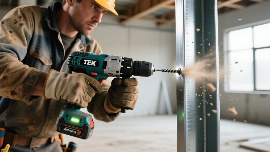
Modern cordless impact drivers and screw guns have transformed steel framing installation, but excessive torque is a leading cause of connection failure. The goal is to seat the screw head flush with the steel surface, creating a slight 'dimple' without tearing the surrounding metal.
- Set the Clutch Correctly: If using a standard drill/driver, set the torque clutch to a medium-low setting (typically 8-12 on a 20-setting collar) for 20-gauge, and 12-16 for 16-gauge. The clutch must slip the moment the screw head seats. If you are using an impact driver, you must use specialized self-feeding collated screw systems with depth-sensitive nose cones to prevent over-driving.
- Verify Minimum Edge Distance: The American Institute of Steel Construction (AISC) mandates specific edge distances to prevent tear-out. For #8 and #10 screws in steel framing, maintain a minimum distance of 1.5 times the screw diameter from the edge of the connected part. In practical terms, keep all screws at least 1/2 inch away from the open edge of a stud flange.
- Screw Spacing and Seam Stitching: For composite wall assemblies, studs are typically spaced 16 inches on center (o.c.). However, when splicing tracks or joining built-up headers, stitch screws must be placed at a maximum of 12 inches o.c. along the seam, with the first screw located no more than 2 inches from the end of the splice.
Troubleshooting Grade-Specific Field Failures
When steel framing installation goes wrong, the root cause is almost always a mismatch between the steel's physical properties and the installation technique. Use this diagnostic matrix to resolve common field issues.
Symptom: Screw Spin-Out (Stripped Hole)
Cause: Using a #3 or #4 drill point on 20-gauge or 25-gauge steel, or applying excessive RPM which melts the zinc and reams the hole before the threads engage.
Fix: Switch to a #1 or #2 point screw. Lower the drill RPM. If the hole is already stripped, insert a structural stitch screw at a 15-degree angle to bypass the compromised zone, or use a larger diameter toggle bolt if the connection allows.
Symptom: Web Crippling at Track Connections
Cause: Installing heavy point loads (like joist hangers or concentrated header connections) on high-strength (Grade 80) but thin-webbed (18 or 20-gauge) studs without adequate web stiffeners.
Fix: Install manufactured steel web stiffeners or field-cut blocks of the same gauge track, screwed securely to the web directly beneath the point of load transfer to distribute the shear force.
Symptom: Track Buckling During Layout
Cause: Fastening the bottom track to a highly uneven concrete slab using powder-actuated tools (PAT) with excessive drive pins, causing the thin flanges of 20-gauge non-structural track to warp and buckle upward.
Fix: Switch to concrete screws (like Tapcon-style anchors) pre-drilled through the track, or use a PAT with a lower velocity load (yellow or green instead of red). Shim the low spots in the concrete with non-compressible steel shims before driving the fastener to maintain a perfectly flat track plane.
Precision in steel framing installation is not just about plumb lines and level tracks; it is about respecting the material science of the steel itself. By aligning your fastener selection, drill speeds, and structural detailing with the specific ASTM grades and mil thicknesses of your CFS members, you ensure a framing assembly that meets both the engineering specifications and the rigorous demands of modern commercial construction.
Written by
Sarah WhitfieldSarah Whitfield is a chartered quantity surveyor (MRICS) and construction cost analyst with 15 years of experience in material pricing, procurement strategy, and project budgeting. She earned her degree in Construction Management from the University of Reading (UK) and has worked on projects ranging from $2M custom homes to $180M mixed-use developments across North America and Europe. Sarah currently leads cost estimating for BuildMat Insight, maintaining a proprietary database of 4,000+ material price points updated quarterly. She is a frequent contributor to RSMeans cost data panels and has presented at the International Cost Engineering Council (ICEC) congress. Based in Denver, CO, Sarah is an avid trail runner and volunteer mentor for Women in Construction.
More from Sarah Whitfield
View all
Wood & Lumber
What Are the Different Types of Wood? A Builder's Guide
Compare structural softwoods, finish hardwoods, and engineered lumber. Analyze Janka ratings, MOE values, and 2026 pricing for construction.
Aug 4, 2026
Walls & Panels
Steel Framing vs Wood Framing: Corrosion and Moisture Defense
Compare steel framing vs wood framing for moisture resistance. Learn about galvanized coatings, condensation risks, and corrosion protection strategies.
Jul 21, 2026

Stone & Masonry
How to Cut Stone Veneer: Wet Saw vs Grinder Comparison
Compare the best tools for cutting stone veneer. We review wet saws, angle grinders, and chop saws to help you achieve clean, chip-free cuts.
Jul 21, 2026