Steel Framing Plan vs Wood and Concrete: Design & Cost Guide
Decode a steel framing plan against wood and concrete. Compare load paths, connection details, tolerances, and 2026 framing costs for commercial builds.

Decoding the Blueprint: Material-Specific Framing Logic
Reviewing a steel framing plan requires a fundamentally different analytical approach than reading wood or concrete structural drawings. While the end goal—transferring gravity and lateral loads to the foundation—remains constant, the mechanics, tolerances, and connection philosophies diverge sharply. In 2026, as hybrid structures and mid-rise cold-formed steel (CFS) buildings dominate commercial and multi-family sectors, general contractors and detailers must understand how a steel framing plan dictates field execution compared to traditional dimensional lumber or cast-in-place concrete.
This guide dissects the structural, logistical, and financial differences embedded in framing plans across these three primary materials, providing actionable frameworks for plan review and cost estimation.
The Anatomy of a Steel Framing Plan vs. Wood
When transitioning from a wood framing plan to a steel framing plan, the most immediate difference is the level of connection detailing. A wood plan often relies on prescriptive nailing schedules (e.g., 16d common nails at 16 inches on center). A steel framing plan, governed by the American Iron and Steel Institute (AISI) standards, requires explicit screw, pin, or weld schedules for every joint.
Dimensional Tolerances and Shrinkage
Wood framing plans must account for cross-grain shrinkage. In a three-story wood-framed building, cumulative shrinkage can reach 1.5 inches, requiring the architect to detail slip joints for plumbing and cladding. Conversely, a steel framing plan operates on the premise of zero shrinkage. Cold-formed steel (CFS) studs, typically ranging from 20-gauge (33 mil) to 12-gauge (68 mil) with yield strengths of 33 ksi or 50 ksi, maintain exact dimensional stability. This allows steel plans to integrate tighter tolerances for elevator shafts and stairwells, eliminating the need for the shrinkage compensation details cluttering wood blueprints.
Unlike wood top plates, a steel framing plan will frequently specify a deflection track (e.g., a 1.5-inch leg bypass clip system) at the top of non-load-bearing partition walls. This allows the primary structure to deflect under live loads without crushing the interior CFS studs—a detail entirely absent in wood framing plans.
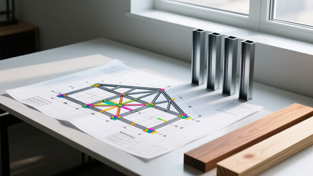
Structural Load Paths: Steel vs. Concrete Framing Plans
Concrete framing plans focus heavily on rebar schedules, embedment depths, and pour sequences. Steel framing plans prioritize the continuity of the load path through mechanical fasteners. When comparing the two, the lateral force-resisting system (LFRS) dictates the drawing complexity.
| Metric | Steel Framing (CFS) | Wood Framing | Concrete (Cast-in-Place) |
|---|---|---|---|
| Primary Lateral System | Strap-braced shear walls or X-bracing | Wood structural panels (OSB/Plywood) | Shear walls or moment frames |
| Plan Detailing Focus | Hold-downs, strap splices, screw counts | Nail schedules, blocking, hold-downs | Rebar laps, embed plates, pour stops |
| Weight (per sq ft of wall) | 4 - 6 lbs | 5 - 8 lbs | 40 - 55 lbs |
| Fire Rating Assembly (2-hr) | Dual-layer 5/8" Type X gypsum | Dual-layer 5/8" Type X or heavy timber | Inherent (min 5" thickness) |
For structural engineers, the American Iron and Steel Institute (AISI) provides the governing criteria for CFS load paths, while the American Wood Council (AWC) and the Concrete Reinforcing Steel Institute (CRSI) govern their respective materials. Reviewing a concrete plan requires checking for shoring and reshoring schedules due to the curing time of the slab; a steel framing plan assumes immediate load-bearing capacity upon fastening, drastically altering the critical path schedule.
Translating the Plan: Connection Details and Fasteners
The most frequent point of failure during construction occurs when field crews misinterpret connection details. The fastening ecosystem varies wildly across materials.
Steel Connections
A steel framing plan will specify self-drilling screws (e.g., #10 or #12 hex washer head), powder-actuated pins (like Hilti X-HSN), or structural clips from manufacturers like Simpson Strong-Tie or Dietrich Industries. For shear walls, the plan will detail flat strap tension members and specify the exact number of screws for the strap-to-stud connection. Missing a single screw in a 4-screw splice can reduce the capacity of the shear wall by 25%.
Wood Connections
Wood plans rely on friction and shear capacity of nails. The detailing is often less precise regarding exact placement, relying instead on minimum edge distances and spacing grids. However, wood plans require meticulous attention to hardware (hurricane ties, joist hangers), which must be matched to the specific wood species and moisture content.
Concrete Connections
Concrete plans dictate cast-in-place embeds or post-installed anchors (epoxy or wedge anchors). The critical detail here is the rebar development length and lap splice zones, which must be strictly adhered to before the concrete truck arrives.
When a steel framing plan interfaces with a concrete foundation, detailers must specify a physical barrier (e.g., sill sealer or a galvanized track per ASTM A653 G60 minimum). Direct contact between CFS and uncured or moisture-rich concrete accelerates galvanic corrosion, a failure mode rarely encountered in wood-to-concrete interfaces.
2026 Cost and Schedule Implications from the Blueprint
The complexity of a framing plan directly correlates to field labor costs. While material prices fluctuate, the labor required to execute the plan's details is the primary budget driver.
- Cold-Formed Steel Framing: $9.50 – $14.50 per sq. ft. (material + labor). The high precision required for CFS track and stud assembly, plus the time-consuming nature of driving hundreds of self-drilling screws per wall, increases labor costs. However, off-site panelization can reduce field time by 30%.
- Wood Framing: $6.50 – $11.00 per sq. ft. Wood remains the most cost-effective for low-rise residential due to rapid cutting and pneumatic nailing, though material waste and vulnerability to weather delays add hidden costs.
- Concrete Framing: $14.00 – $19.50 per sq. ft. The high cost of forming, pouring, and stripping, combined with the heavy equipment required, makes concrete the most expensive framing option, justified only by its superior acoustic, thermal, and life-cycle performance.
Common Blueprint Translation Errors to Avoid
When executing a steel framing plan, field supervisors frequently encounter specific edge cases that do not exist in wood or concrete. Use this troubleshooting framework during plan review:
- Symptom: Studs buckling under vertical load before drywall is installed.
Cause: The plan specified non-load-bearing studs (e.g., 20-gauge 250S162) in a load-bearing zone, or omitted required lateral bracing (bridging/strap bracing) at mid-height.
Fix: Verify the stud designation on the plan against the structural load schedule. Ensure continuous lateral bracing is installed per the engineer's spacing requirements (typically every 4 feet for weak-axis bracing). - Symptom: Drywall cracking at the ceiling line in multi-story CFS buildings.
Cause: The framing plan failed to detail a deflection gap or specify a slide clip at the top track of interior partitions to accommodate live-load floor deflection.
Fix: Install a bypass clip system (e.g., Simpson Strong-Tie SLPC) that allows the top track to move independently of the studs, maintaining a 1-inch deflection gap. - Symptom: Inability to route MEP (Mechanical, Electrical, Plumbing) through load-bearing steel studs.
Cause: Unlike wood, where field crews can drill holes on-site, cutting flanges on CFS load-bearing studs compromises structural integrity.
Fix: Cross-reference the steel framing plan with the MEP drawings early. Order studs with factory-punched web knockouts sized for specific conduit and pipe diameters, or utilize structural headers around large duct openings.
Summary Checklist for Plan Review
Before breaking ground or ordering materials, ensure your pre-construction team has validated the following elements specific to the chosen material's framing plan:
- Steel: Verify hold-down anchor bolt embedment depths, confirm strap splice screw counts, and check for deflection clips at all non-load-bearing partitions.
- Wood: Confirm shrinkage compensation details at vertical risers, verify fire-blocking at concealed spaces, and check hold-down continuity from roof to foundation.
- Concrete: Review pour sequences, verify rebar lap lengths at shear wall boundaries, and confirm the location of all embedded steel connection plates.
Mastering the nuances of a steel framing plan compared to its wood and concrete counterparts prevents costly field rework, ensures structural compliance, and optimizes the 2026 construction budget.
Written by
Elena RodriguezElena Rodriguez is a civil engineer and technical writer specializing in concrete technology, masonry systems, and ASTM/ACI compliance. She earned her B.S. in Civil Engineering from Texas A&M University and spent a decade at a materials testing laboratory, performing over 2,000 concrete compressive strength tests and masonry prism evaluations. Elena is an ACI-certified Field Testing Technician (Grade I) and a member of ASTM Committee C12 on Natural Building Stone. She currently consults on forensic engineering cases involving concrete failures and moisture intrusion. Based in San Antonio, TX, Elena is a proud member of the Society of Women Engineers (SWE) and coaches her daughter's FIRST Robotics team.
More from Elena Rodriguez
View all
Walls & Panels
Cost Analysis: Light Gauge Steel Framing Advantages and Disadvantages
Evaluate light gauge steel framing advantages and disadvantages through a strict cost analysis lens, comparing material, labor, and lifecycle expenses.
Aug 4, 2026
Walls & Panels
Gypsum Board Types: Exact Specifications, Thickness & Dimensions
Compare standard, Type X, and moisture-resistant gypsum board types. Get exact specifications, thicknesses, dimensions, and ASTM standards for your project.
Aug 4, 2026
Fire Resistance
Best Fire-Resistant Outdoor Decking Materials: 2026 Buyer Guide
Discover the best fire-resistant outdoor decking materials for 2026. Compare Class A PVC, aluminum, and hardwood options for WUI compliance and safety.
Aug 4, 2026